MOJ
eISSN: 2576-4519


Research Article Volume 9 Issue 1
1Department of spinal neurosurgery, Romodanov Neurosurgery Institute, Ukraine
2Restorative Neurosurgery Department, Romodanov Neurosurgery Institute, Ukraine
3Biomechanical Laboratory, Sytenko Institute of Spine and Joint Pathology, Ukraine
Correspondence: Oleksii S. Nekhlopochyn, MD, PhD, Senior researcher of Department of spinal neurosurgery, Romodanov Neurosurgery Institute of National Academy of Medical Sciences of Ukraine, P. Mayborody str. 32., 04050, Kiev, Ukraine, Tel +380 44 483-94-13
Received: January 30, 2025 | Published: February 13, 2025
Citation: Nekhlopochyn OS, Verbov VV, Cheshuk IV, et al . Comparative biomechanical analysis of short transpedicular fixation methods for burst fractures in the thoracolumbar junction under rotational loads. MOJ App Bio Biomech. 2025;9(1):15-20. DOI: 10.15406/mojabb.2025.09.00219
This study focused on evaluating the biomechanical behavior of short-segment transpedicular fixation for burst fractures at the thoracolumbar junction under pure rotational loading. A finite element model of the T9–L5 spinal segment, including a burst fracture at T12, was constructed to compare four fixation configurations: short and long pedicle screws, with or without an intermediate screw in the fractured vertebra.
The findings highlight that short-segment fixation without intermediate screws subjects both the metal hardware (rods and screws) and the adjacent vertebrae to higher stress levels. Notably, the rods can approach their tensile strength limit, indicating a higher risk of implant failure. Introducing an intermediate screw at T12, particularly in combination with longer screws, significantly reduces stress on both bony structures and the fixation system. This approach distributes the rotational load more effectively, minimizing localized overloading and consequently lowering the likelihood of fixation failure.
From a clinical perspective, these results suggest that a combination of longer pedicle screws and an intermediate screw may offer superior mechanical stability for burst fractures at the thoracolumbar junction under rotational stress. However, because the model employs several simplifying assumptions (e.g., homogeneous, isotropic material properties; quasi-static loading), further research is warranted to validate these findings and to explore the full spectrum of loading scenarios.
Keywords: thoracolumbar junction, biomechanics, burst fracture, finite element analysis, spinal stabilization
When analyzing the biomechanical characteristics of the thoracolumbar spine, it is universally accepted and virtually undisputed that, owing to the rib cage, the relatively small height of the intervertebral discs, and specific ligamentous features, the thoracic region is considerably more rigid in terms of permissible physiological range of motion compared to the lumbar region.1,2 This observation underpins, to a large extent, the strategy and tactics of surgical stabilization procedures for traumatic injuries in this area and is also of significant importance in designing rehabilitation measures.3,4
At the same time, it remains relatively unknown that the thoracic spine, in fact, exhibits a substantially greater range of rotational mobility compared with the lumbar spine.5–7 This distinct feature is largely determined by the specific anatomical and ligamentous configuration of the thoracic region. In particular, the frontal-plane orientation of the thoracic facet joints provides a greater potential for rotational movements. Despite the stabilizing effect of the rib cage, the total rotational range across T1–T12 may reach 25–40°. Notably, the upper and mid-thoracic vertebrae (T1–T6) demonstrate considerably higher mobility, with rotational amplitude of approximately 4–6° at each functional level. In the lower thoracic segments (T7–T12), this value decreases (to 2–3°) as they gradually assume morphological characteristics of the lumbar spine.8
The facet joints of the lumbar vertebrae, oriented closer to the sagittal plane, account for a predominance of flexion, extension, and lateral bending in this region; however, they provide a relatively limited capacity for rotation. According to various authors, the total rotational range of motion in the lumbar spine varies between 5° and 13°. Most of this rotation occurs in the segments L1–L4 (1°–2° per segment), whereas at L5–S1, it can be as little as 1°. This restriction of rotational movement is believed to serve as a protective mechanism that reduces the risk of injury to the intervertebral discs and facet joints.9,10
Of particular importance is the thoracolumbar junction, where the orientation of the facet joints gradually shifts from the frontal to the sagittal plane. Rotational mobility at this level typically does not exceed 2°–3°, but it may vary depending on the individual condition of the ligamentous and muscular systems and on compensatory biomechanical mechanisms. If the upper thoracic segments have insufficient mobility, the body may occasionally “transfer” rotational load to the T10–L1 region.11
Because the thoracic spine can accommodate a greater degree of rotation than the lumbar spine, once surgical stabilization is performed in the thoracolumbar junction, during the postoperative period—when the patient regains or attempts to use natural rotation in this area—the torsional forces become concentrated on the stabilization system itself.
This issue has significant practical relevance for several reasons. First, the thoracolumbar junction is one of the most vulnerable regions of the spine: according to the literature, about 46.5% of all vertebral fractures occur at the T11–L2 level.12 Second, the specifics of stabilization in this region continue to be a subject of intense debate in contemporary vertebrology.
Over the past few decades, there has been a notable shift in the paradigm of spinal stabilization approaches for traumatic injuries. With the advent of more modern and reliable fixation systems, the concept of stabilization without fusion and the trend toward minimizing the extent of instrumentation have become increasingly widespread.13,14 Such an approach yields significant advantages when assessing long-term treatment outcomes: the maximum possible number of functionally active motion segments is preserved, and if successful fracture consolidation is achieved, remobilization of the stabilized region remains feasible.15
At the same time, the specific biomechanical features of the thoracolumbar junction —which contribute to the high incidence of injuries in this area—necessitate the use of more mechanically robust fixation systems compared to other spinal regions.16 Numerous studies indicate an increased risk of failure with short four-screw fixation specifically at the thoracolumbar junction. Such failure can result in early mechanical complications (screw migration, rod breakage, loss of correction, etc.) and, consequently, may require revision surgery.17
Hence, when selecting a stabilization method for the thoracolumbar junction, one faces a complex challenge: on the one hand, the goal is to preserve physiological mobility and minimize the extent of fixation, while on the other, it is imperative to ensure the reliability of the construct given the increased biomechanical loads in this region. Optimal solutions typically involve a multifaceted approach, taking into account the fracture type, bone quality, patient age, the presence of osteoporosis, and other relevant factors.18,19
One of the most characteristic types of injury at the thoracolumbar junction is the “burst” fracture (type A3 or A4 according to the AOSpine classification). This prevalence is largely explained by the anatomical curvature in the T11–L2 region, where the transition from thoracic kyphosis to lumbar lordosis creates a relatively “straight” spinal segment.20 When the physiological curve is thus “straightened,” compressive loads during trauma are not adequately redistributed, increasing the risk of burst fractures.
Within the framework of minimizing surgical intervention, one of the contemporary methods for correcting such injuries is short-segment fixation with intermediate pedicle screws. These screws are often shorter than standard implants and are placed directly into the injured vertebral body. According to several researchers, this approach offers clinical outcomes comparable to the classic eight-screw stabilization technique, which extends two levels above and two levels below the injured vertebra.21–23
However, a review of the available literature did not identify comprehensive studies investigating in detail the biomechanical rationale and optimal techniques for this type of six-screw fixation. Moreover, despite the unique rotational loading characteristics of the thoracolumbar junction, this aspect frequently remains outside the main focus of research.
The aim of this study was to investigate the stress–strain state of a thoracolumbar spine model with a burst fracture of the T12 vertebra under short-segment transpedicular fixation with various configurations, subjected to rotational loading.
A finite element mathematical model of the human thoracolumbar spine with a burst fracture of the Th12 vertebra was developed in the Biomechanics Laboratory of Sytenko Institute of Spine and Joint Pathology National Academy of Medical Sciences of Ukraine. A detailed description of the model and its characteristics has been presented in previous publications.24,25
A burst fracture was simulated by dividing the T12 vertebral body into separate fragments using multiple planes. The gaps between these fragments were filled with a material that replicated the interfragmentary regenerate.
Four transpedicular fixation configurations were modeled for the two vertebrae adjacent to the injured one. These configurations involved either short or long fixation screws passing through the anterior surface of the vertebral body, with or without the placement of two intermediate screws in the T12 vertebra. As an example, Figure 1 shows spondylograms of patients who underwent surgery for a burst fracture of a single vertebra in the thoracolumbar region, treated with short fixation both without and with intermediate screws.
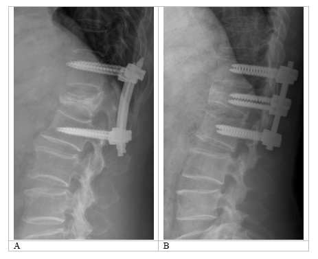
Figure 1 Examples of spondylograms of patients following surgical treatment for burst fractures of the thoracolumbar region. (А) Short fixation without intermediate screws; (B) Short fixation with intermediate screws.
During the modeling process, it was assumed that the material is homogeneous and isotropic, consistent with generally accepted principles of finite element analysis in similar studies.26 This approach makes it possible to objectively evaluate the principal mechanical properties and behavior of biological structures, as detailed in earlier publications.27 A 10-node tetrahedral element with quadratic approximation was chosen as the finite element. The mechanical properties of the biological tissues (cortical and cancellous bone, intervertebral discs) were adopted from.28–30 The metallic components of the instrumentation were made of titanium. The mechanical characteristics of artificial materials were selected according to technical literature data.31 The parameters used in the analysis included E (Young’s modulus) and ν (Poisson’s ratio). The data on the mechanical characteristics of the materials are provided in Table 1.
|
Material |
Young’s modulus (MPa) |
Poisson’s ratio |
|
Cortical bone |
10,000 |
0.3 |
|
Cancellous bone |
450 |
0.2 |
|
Articular cartilage |
10.5 |
0.49 |
|
Intervertebral discs |
4.2 |
0.45 |
|
Interfragmentary regenerate |
1 |
0.45 |
|
Titanium VT-16 |
110,000 |
0.3 |
Table 1 Mechanical characteristics of the materials used for modeling
The stress–strain state of the models was analyzed under rotational loading. For this purpose, a torque of 10 Nm was applied to the T9 vertebral body. The model was rigidly fixed along the distal surface of the L5 disc. The loading scheme of the models is shown in Figure 2A.
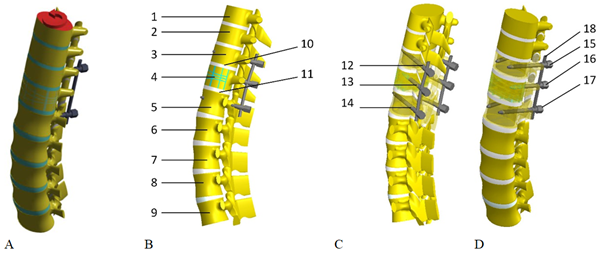
Figure 2 Schematic representation of the finite element model under loading (A) and the location of the control points (B–D): 1 – T9 vertebral body; 2 – T10 vertebral body; 3 – T11 vertebral body; 4 – T12 vertebral body; 5 – L1 vertebral body; 6 – L2 vertebral body; 7 – L3 vertebral body; 8 – L4 vertebral body; 9 – L5 vertebral body; 10 – inferior endplate of the T11 vertebral body; 11 – superior endplate of the L1 vertebral body; 12 – screw entry in the T11 arch; 13 – screw entry in the T12 arch; 14 – screw entry in the L1 arch; 15 – screws in the T11 vertebral body; 16 – screws in the T12 vertebral body; 17 – screws in the L1 vertebral body; 18 – support rods.
For convenience in analyzing changes in the stress–strain state of the models depending on the transpedicular fixation method, stress values were measured at a series of control points (Figure 2B-D).
The stress–strain state of the models was investigated using the finite element method. The von Mises stress23 served as the evaluation criterion for the stress state of the models. Modeling was performed using the SolidWorks (Dassault Systèmes, France) computer-aided design system, and calculations of the stress–strain state were carried out with the CosmosM software package.32
In the first stage of the study, the stress–strain state of the thoracolumbar spine model with a burst fracture of the T12 vertebral body was analyzed under rotational loading. Short screws were used for transpedicular fixation without fixation of the T12 vertebra. Figure 3 shows the stress distribution in the model.
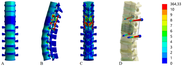
Figure 3 Stress distribution in the thoracolumbar spine model with a burst fracture of the T12 vertebral body under rotational loading. Transpedicular fixation with short screws, without intermediate: (A) anterior view; (B) lateral view; (C) posterior view; (D) Screws.
Under rotational loading in the model with short transpedicular fixation using short screws, the maximum stress of 32.8 MPa arises in the lower thoracic region, specifically in the T12 vertebral body. In the adjacent vertebrae (T11 and L1), the stress levels are three times lower—9.1 MPa and 10.2 MPa, respectively. In the lumbar region, the stress level gradually decreases, reaching a minimum of 4.0 MPa in the L5 vertebral body.
Around the fixation screws, the maximum stress of 16.2 MPa is observed in the T11 vertebral arches, whereas it is slightly lower—14.8 MPa—in the L1 arches. A similar pattern occurs on the screws themselves: the stress on the T11 screws is higher than on the L1 screws, measured at 86.9 MPa and 61.3 MPa, respectively. The most stressed elements of the metal construct are the rods, where the stress reaches 457.0 MPa.
Figure 4 presents the stress–strain state of the thoracolumbar spine model with a burst fracture of the T12 vertebral body under rotational loading. In this case, transpedicular fixation is performed with long screws, without fixation of the T12 vertebra.
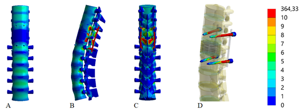
Figure 4 Stress distribution in the thoracolumbar spine model with a burst fracture of the T12 vertebral body under rotational loading. Transpedicular fixation with long screws, without intermediate: (A) anterior view; (B) lateral view; (C) posterior view; (D) Screws.
Using long transpedicular screws under rotational loading, compared with the model using short screws, leads to a decrease in the stress levels in the most heavily loaded components of the model. Specifically, in the vertebral bodies at the instrumentation level, the largest reduction in stress occurs in the T12 body, decreasing to 26.5 MPa. In the adjacent vertebral bodies (T11 and L1), stresses drop to 8.5 MPa and 10.5 MPa, respectively. In the lumbar spine, specifically the L2–L4 vertebral bodies, stresses decrease only slightly, ranging from 7.2 MPa to 7.5 MPa, with no observed changes in the other vertebrae. Around the fixation screws, stress is reduced in the T11 arches to 15.5 MPa, but increases slightly to 15.9 MPa in the L1 arches. On the screws themselves, the stress level decreases to 80.9 MPa and 55.7 MPa at T11 and L1, respectively. On the rods, the maximum stress measured is 440.5 MPa, which is also lower than in the previous model.
Next, the effect of additional fixation of T12 was investigated on the stress distribution in the thoracolumbar spine model with a burst fracture of the T12 vertebral body under rotational loading, using transpedicular fixation with short screws. Figure 5 depicts the stress distribution in this model.
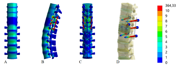
Figure 5 Stress distribution in the thoracolumbar spine model with a burst fracture of the T12 vertebral body under rotational loading. Transpedicular fixation with short screws, with intermediate: (A) anterior view; (B) lateral view; (C) posterior view; (D) Screws.
The modeling results showed that, under rotational loading, using additional T12 vertebral fixation in combination with short transpedicular screws decreases the stress level at all control points on the bony elements of the model compared to the model without T12 fixation. The only exceptions are the T9, T10, and L5 vertebral bodies, where the stress values remained unchanged. Around the fixation screws in the vertebral arches, stresses decreased to 12.5 MPa in T11 and increased to 20.2 MPa in L1. This occurs due to the rigid transfer of load through T12, which is stabilized with additional screws. The stress around these screws in the T12 arches was measured at 11.6 MPa. On the screws themselves in T12, the stress did not exceed 42.6 MPa, the lowest value among all fixation screws in the model; stress levels on the screws also decreased to 80.8 MPa in T11 and to 53.5 MPa in L1. Notably, there was a threefold reduction in the stress on the support rods, where the maximum measured value did not exceed 313.1 MPa.
Figure 6 illustrates how the presence of additional T12 fixation affects the stress distribution in the model using long-screw transpedicular fixation.
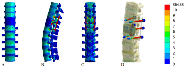
Figure 6 Stress distribution in the thoracolumbar spine model with a burst fracture of the T12 vertebral body under rotational loading. Transpedicular fixation with long screws, with intermediate: (A) anterior view; (B) lateral view; (C) posterior view; (D) Screws.
The table 2 presents the stress values (MPa) at multiple control points in a thoracolumbar spine model under rotational loading, comparing four variants of transpedicular fixation: using short or long screws, with or without intermediate screws in the fractured vertebra (T12).
|
Control points |
Stress (MPa) |
||||
|
Model without intermediate screws |
Model with intermediate screws |
||||
|
No |
Zone |
Short screws |
Long screws |
Short screws |
Long screws |
|
1 |
T9 vertebral body |
4.5 |
4.5 |
4.5 |
4.5 |
|
2 |
T10 vertebral body |
3.7 |
3.7 |
3.7 |
3.7 |
|
3 |
T11 vertebral body |
9.1 |
8.5 |
7.5 |
7 |
|
4 |
T12 vertebral body |
32.8 |
26.5 |
27.8 |
22.6 |
|
5 |
L1 vertebral body |
10.2 |
9.5 |
9 |
8.7 |
|
6 |
L2 vertebral body |
7.9 |
7.5 |
7.5 |
7.3 |
|
7 |
L3 vertebral body |
8 |
7.4 |
7.3 |
7.1 |
|
8 |
L4 vertebral body |
7.4 |
7.2 |
7.3 |
7 |
|
9 |
L5 vertebral body |
4 |
4 |
4 |
4 |
|
10 |
Inferior endplate of T11 |
5.5 |
5.3 |
4.8 |
6.2 |
|
11 |
Superior endplate of L1 |
7.1 |
7.1 |
7.3 |
6.4 |
|
12 |
Screw entry in T11 arch |
16.2 |
15.5 |
12.5 |
12 |
|
13 |
Screw entry in T12 arch |
- |
- |
11.6 |
12.2 |
|
14 |
Screw entry in L1 arch |
14.8 |
15.9 |
20.2 |
16.1 |
|
15 |
Screws in T11 vertebral body |
86.9 |
80.9 |
80.8 |
74.1 |
|
16 |
Screws in T12 vertebral body |
- |
- |
42.6 |
42.6 |
|
17 |
Screws in L1 vertebral body |
61.3 |
55.7 |
53.5 |
48.4 |
|
18 |
Rods |
457 |
440.5 |
313.1 |
296 |
Table 2 Stress (MPa) under rotational loading in thoracolumbar spine models with T12 burst fracture at using different transpedicular fixation methods
Note: A dash (–) indicates that no screws were placed in T12 in those particular fixation models.
As previously noted, when analyzing various loading modes of a stabilized spine, rotational loads traditionally receive relatively little attention. Moreover, in the limited number of studies where this issue is addressed to some degree, it is evident that the method of applying rotational forces to the spine model differs substantially from that used in our research.
For example, in the study by T. Wang et al., a rotational load was simulated by applying a moment of 1 N·m together with an axial load of 150 N when examining the effects of different pedicle screw trajectories in short-segment fixation of burst fractures at the thoracolumbar junction.33 In the work of N. Nishida et al., which explored how the extent of fixation influences load distribution in implants and vertebrae, an axial load of 30 N and a moment of 1 N·m were utilized.34 Another study by Recep Basaran et al., comparing short versus long fixation in posterior spinal fusion for thoracolumbar fractures, generated a rotational load by applying a moment of 5.5 N·m along with an axial load of 400 N.35 In other words, most available publications focus on combined loading scenarios where axial (compressive) forces predominate, while the rotational component is relatively minor.
In contrast, we adopted a different approach grounded in our own clinical observations. In cases where the patient could pinpoint the exact moment of “fragmentation” (failure) of the fixation system—often reported as a sensation of a “crunch,” “shooting” pain, or acute discomfort—it was noted that such events typically occurred while the patient was lying down. Most frequently, this took place when the patient, keeping the pelvis stationary, attempted to reach for an object, thus provoking a twisting movement. Therefore, we found it appropriate to focus our analysis on “pure” rotational loading (i.e., without a significant axial component).
This research design is logically justified. Indeed, rotation of the spine in the supine position may pose a higher risk for fixation systems (screws, rods, plates) for several reasons. First, when upright (standing), the axial load from body weight and gravity compresses the intervertebral discs and facilitates tighter contact of the facet (zygapophyseal) joints.36 This not only decreases the range of rotational motion but also “locks” the facets due to their specific geometry, allowing natural structures to absorb a portion of the rotational load and thereby reducing stress on the implant.37
Second, in the horizontal position, the axial load is effectively removed, causing both the discs and facet joints to lose a substantial part of their stabilizing function. Without compressive “contact,” the facets cease to act as “blockers” of excessive rotational movement, and the intervertebral discs undergo less compression—leading to increased mobility among the vertebrae. Consequently, the fixation system must bear the full burden of limiting rotation, raising stress levels on the screws and rods and thus heightening the likelihood of fatigue-related failure.38,39
Third, there is a pronounced increase in the “lever arm” for rotation when lying down. With the pelvis and lower limbs relatively fixed, the shoulder girdle and upper torso are free to rotate more extensively. This configuration creates a substantial moment of force at the thoracolumbar junction, where the analyzed fixation devices are located. By contrast, when standing, rotational stress is distributed more evenly across several spinal segments, and additional stabilizing contributions from the muscles and ligaments help mitigate peak loads on the fixation system.40
Therefore, the combination of these three factors—reduced axial compression, diminished natural rotational limiters (facet joints and intervertebral discs), and an enlarged rotational lever arm—explains why rotational movements performed in the supine position can be more damaging to the fixation system than similar movements performed standing. In such circumstances, the implant must fully counter the torsional load, significantly increasing the probability of mechanical failure of screws, rods, and other hardware components.41
The analysis of our modeling findings indicates that, under rotational loading, using a short osteosynthesis system for vertebrae with burst fractures—without additional fixation of the injured vertebra—leads to a marked overloading of the implant components. Notably, this effect persists regardless of the screw length in the adjacent vertebrae. The highest stress levels occur in the rods, where the values approach the tensile strength limit of surgical-grade steel. Substantial loads were also recorded in the bony structures of the model. These results partly explain the relatively high incidence of fixation failure when a short stabilization system is used to treat burst fractures in the thoracolumbar region. At the same time, introducing intermediate screws can, in certain cases, offset these shortcomings and may be regarded as a viable alternative to the extended (eight-screw) fixation approach.
In developing the model, the material was treated as homogeneous and isotropic. The poroviscoelastic properties of spinal tissues were disregarded due to the use of a quasi-static approach for load application. Given the considerable individual variability in both mechanics and anatomy, tailoring model parameters for a specific patient was deemed unnecessary, as the primary objective of this study was to evaluate stress distribution under various loading conditions and potentially extrapolate the findings to the broader population. For these reasons, the adopted simplifications appear both justified and reasonable.
The results obtained in this study do not provide a definitive basis for concluding which stabilization method is more appropriate in cases of burst fractures at the thoracolumbar junction. Nonetheless, further investigations—including analyses involving a full range of loading patterns—will be needed to more objectively assess the potential risks and benefits associated with each surgical approach.
Under rotational loads, using short instrumentation for osteosynthesis of vertebrae with burst fractures—without additional fixation of the injured vertebra—leads to overloading of the metal hardware components, regardless of the screw length in the adjacent vertebrae. In contrast, employing longer pedicle screws along with an intermediate screw for the T12 vertebra proved to be the most optimal approach in terms of stress distribution for both the metal construct and the bony elements of the model.
None.
None.
The authors declare that there are no conflicts of interest.

©2025 Nekhlopochyn, et al. This is an open access article distributed under the terms of the, which permits unrestricted use, distribution, and build upon your work non-commercially.