Journal of
eISSN: 2373-4345


Research Article Volume 1 Issue 4
1Department of Dental Biomaterial, Faculty of Dentistry, Mansura University, Egypt
2Department of Mechanical Engineering, National Research Centre, Egypt
Correspondence: Salma M Fathy, Department of Dental Biomaterial, Faculty of Dentistry, Mansura University, Mansoura, Daqahlia 35516, Egypt, Tel 201000000000
Received: August 03, 2014 | Published: August 25, 2014
Citation: Fathy SM, Anwar MIE, Fallal AAE, et al. Three-dimensional finite element analysis of lower molar tooth restored with fully milled and layered zirconia crowns. J Dent Health Oral Disord Ther. 2014;1(4):89-95. DOI: 10.15406/jdhodt.2014.01.00022
Comparing the principle stresses distributions for both fully milled zirconia (FMZ) crown made of yattria-stabilized zirconia (Y-TZP) and layered crowns made Y-TZP core and feldspathic porcelain veneer using finite element analysis, was shot in this study. A three dimensional finite element model was constructed under ANSYS environment. The natural prepared tooth or titanium (Ti) abutment/implant complex were modeled in 3D on commercial general purpose CAD/CAM software. Crown geometry was acquired by using 3D contact scanner, which goes through successive graphical modification before assembled in a 3D finite element model. Crown made from single material (FMZ) is stiffer than layered one. The crown outer layer (Porcelain) receives more energy and stresses (of order 3.8%) than if it was made from Zirconia. While the crown core (inner part) will receive less stresses (about 38%) and energy if it was coated by Porcelain.
Keywords: finite element method, stress distribution, dental materials, crown, dental implant, fully milled zirconia
The introduction of zirconia (ZrO2) in the field of dentistry as restorative material used for crown core substructure or bridge framework manufacture has been widely expanded.1 Its high flexural strength in comparison to metals2 and other types of ceramics3 has made the manufacture of accurate all-ceramic and long-span restorations possible.4 Over the past two decades improvement in core and veneering ceramic materials together with their manufacture process technique has made these layered restorations successful and reliable.5 However, clinical studies reported fracture incidences for the core and veneering ceramic in alumina-based restorations and predominantly chipping of the veneering ceramics in zirconia-based systems.6−9
The problem of chipping arising in ZrO2 based ceramic restoration is due to propagation of crack parallel to the ZrO2/veneer interface.10 Several studies have been conducted to evaluate the effect of thermally induced failure in such layered restoration.11−13 However this failure may be also attributed to continue exposure of this layered ceramic restoration to cyclic loading in moist oral environment14 or even static loading at its maximum values as this study tries to evaluate. The former two cases may contribute to crack propagation at ZrO2 core/veneer interface as well as the case of thermal stresses.
Most ZrO2 based-ceramic restorations do have other problems such opaqueness of the core, which should be masked with a translucent layer of veneer ceramic to achieve the natural appearance.15 The color of this opaque core significantly influences the color of the ceramic restoration.16 Low temperature degradation (LTD) is another problem accompanying this type of restorations. Where, progressive spontaneous transformation of the metastable tetragonal phase into the monoclinic phase (t-m transformation) happens in the mouth temperature with its wet environment.17 That phenomenon was reported to have progressive drawbacks on ZrO2 core properties.18,19 Zirconia full-coverage restorations without veneering dental porcelain, was recently released. Translucent, FMZ or monolithic zirconia crown has many advantages over the porcelain veneered zirconia copings in that no liability of veneering fracture or chipping as it is already absent. The absence of over layer of porcelain may eliminate the possibility of having internal stresses induced at ZrO2 core/veneer interface.20 In addition to its high translucency that was still higher than layered ceramic crowns even after exposure to ageing using chewing simulator.21
Finite element analysis is an accepted and accurate theoretical technique used in solving engineering problems.22 It has proven to be a reliable method in dentistry, especially in the field of representing the geometry of implant system.23−25 It will provide a reliable and non-complicated technique evaluating the stresses in a complex geometry formed by two types of crowns and other different substructures used in the present study. The aim of this study was to evaluate and compare the maximum and minimum principle stresses for both FMZ and layered zirconia crowns using finite element stress analysis.
Acrylic tooth representing the lower first molar tooth was ground prepared to receive a full coverage restoration made of either FMZ or layered ZrO2 crown. A shoulder finish line was done using tapered diamond stone with flat end. Axial walls were reduced with a 6o angle of inclination and occlusal surface was reduced by about 1.5 mm. Double layer impressions of the lower and upper acrylic teeth models, representing patient with normal occlusion, were recorded using polysiloxane impression materials (Express, 3M/ESPE, St., Paul, MN, USA). Occlusal bite registration was recorded in centric occlusion between upper and lower models and sent to laboratory to fabricate ceramic crown using CAD/CAM technique according to manufacturer’s instructions on working casts.
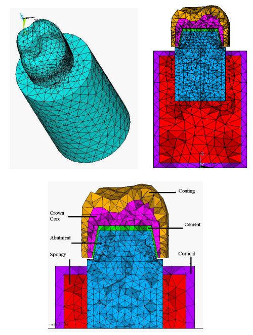
Three dimensional finite element model was constructed under ANSYS vr.9.0 (ANSYS Inc., Canonsburg, PA, USA) environment representing both types of crowns as FMZ and layered one. Crown geometry was acquired by using 3D scanner (Roland Modela - model MDX-15 - Roland DG Corporation of Hamamatsu, Japan) and computer graphics program (Roland´s Dr. PICZA 3™ software), utilizing Roland Active Piezoelectric Sensor as presented. Such scanner produced data file containing a cloud of points coordinates, see Figure 1. An intermediate, software was required (Rhino 3.0-McNeel inc., Seattle, WA, USA) to trim a newly created surface by the acquired points, that was divided into two parts, lower part (not required), and upper part represented the crown surface. Finally, the crown outer surface was closed and filled from its bottom to generate volume representing solid crown. The generated crown contains covering layer of 1mm thickness as a separate part for simulating coating material. Then, the crown geometry was exported to finite element program as SAT file format.26 Two crown materials, Y-TZP and feldspathic porcelain were investigated in this study. Both crowns were cemented with resin cement (Variolink II, Ivoclar Vivadent, Schaan/Liechtenstein). To be mounted on either dentine abutment/root complex or Ti abutment/implant complex. Simulated resin cement layer was of 50 micrometers in thickness. Both complexes were modeled in 3D as elliptic cross sectional bar (8.7 x 7.0mm reduced to 6.3 x 7.0mm linearly along 4.2mm) on commercial general purpose CAD software “AutoDesk Inventor” version 8.0 (Autodesk Inc., San Rafael, CA, USA). Bone geometry was simplified and simulated as cylinder that consists of two co-axial cylinders. The inner one represents spongy bone (diameter 14 mm & height 22mm) that filling the internal space of the other cylinder (shell of 1mm thickness) that represents cortical bone (diameter 16 mm & height 24 mm).27,28 Weighted average properties for tooth dentine & cementum were used for abutment/root complex. All material properties used in this study were listed in Table 1.
The two crowns were subjected to oblique load of 300 N with 45°, and vertical compressive loading of 655 N, at two points, which were selected near the cusp tips of mesiobuccal (MB) cusp (29) and distobuccal (DB) cusp inclines on the occlusal table (equally distributed on four close points), which is too close to implant-abutment complex axis. The base of the finite element models set to be fixed which defined the boundary condition.28
Linear static analysis was performed. The solid modeling and (SOLID45), which has three degrees of freedom (translations in the global directions).30 Mesh density is another relevant parameter, was checked. As the geometries are complex, improving the mesh has the usual effect of improving the results for the discrete model (increasing the obtained stress levels accuracy in regions of high stress gradients). Another effect of increasing the number of elements is to reduce sharp angles created artificially by the process of substituting the geometric model by the mesh, reducing artificial peak stresses by improving the representation of the actual geometry, mesh density is tabulated in Table 2. While Figure 2 illustrates the complete meshed model, and section sowing part of crown, implantabutment, and cement layer elements in different colors.
The bonding simulates perfect osseointegration in which the implant and the surrounding compact bone are fully integrated that neither sliding nor separation in the implant-bone interface is possible, similarly as cement layer bond with either crown and tooth (abutment). Analyzing force transfer at bone-implant interface is an essential step in the overall analysis of loading case, which determines the success or failure of an implant. It has long been recognized that both implant and bone should be stressed within a certain range for physiologic homeostasis. Overload can lead to bone resorption or fatigue failure of the implant, whereas under loading of the bone may cause disuse atrophy and subsequent bone loss.
However, the validity of a linear static analysis is questionable for more realistic situations such as sudden loading. But in such studies the endurance limit (fatigue failure limit), governs most cases of dental analysis. In case of having static stresses lower than endurance limit under worst case of external loads it will be safe from fatigue failure.
|
Material |
Young’s Modulus [MPa] |
Poisson’s Ratio |
|
Cancellous bone |
1,370 |
0.30 |
|
Cortical bone |
13,700 |
0.30 |
|
Implant complex or natural tooth substructure 1. Titanium abutment and fixture 2. Root (weighted average from dentine and cementum) 3. Dentine abutment |
110,000 4,450 18,600 |
0.35 0.30 0.31 |
|
Resin cement (Variolink II) (50 µm cement layer) |
8,300 |
0.30 |
|
Crown materials 1. Zirconia (core) 2. Porcelain (coating) 3. FMZ crown |
210,000 70,000 210,000 |
0.30 0.19 0.30 |
Table 1 Material properties
|
|
Nodes |
Elements |
|
Cortical |
896 |
2,604 |
|
Spongy |
1,761 |
7,697 |
|
Abutment (Ti or Dentine) |
1,226 |
5,697 |
|
Implant (Ti or Root) |
1,758 |
8,389 |
|
Cement layer |
496 |
1,393 |
|
Crown (core) |
1,257 |
5,169 |
|
Crown (coating) |
1,346 |
4,732 |
Table 2 Number of nodes and elements
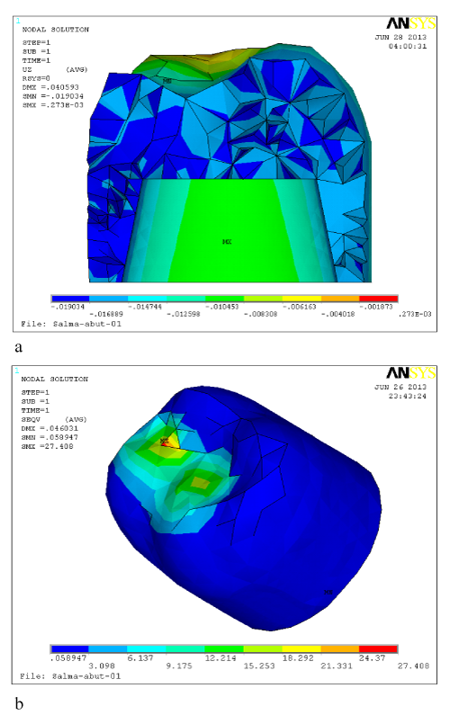
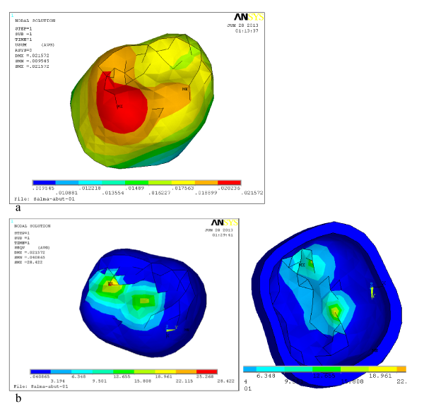
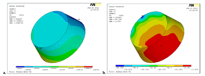
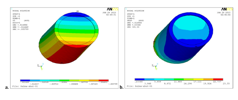
This study includes four combinations of material cases, two types of crowns (monolithic ZrO2, and ZrO2 core layered with porcelain veneer), two types of abutments (dentine and Ti) and two types of roots dental root (weighted average of dentine and cementum), or Ti implant. Each of these cases was subjected to two types of loading (655 N vertical and 300 N oblique) to obtain eight model runs. Each run can produce thousands of graphical results pictures showing all possible types of deformations, strains, and stresses on each part of the studied model. Principal and Von Mises stresses distributions, and deformations in the global Cartesian coordinates, in addition to the equivalent deformation distributions were obtained as pictures for each component of the studied model. Most important deformations/stresses components were presented and discussed here within this research. The FMZ crown showed maximum Von Mises stress values of 86.05 MPa directly under vertical loading and 27.4 MPa under oblique loading at the areas of load application on the slope of MB cusp toward central groove as presented in Figure 3. However the layer of porcelain veneer received higher Von Mises stress by about 3.7% than FMZ and it reduced its value transferred to ZrO2 core by about 33.9% (to be 59.06 MPa). Figure 4 illustrate deformation and stress distribution on the porcelain layer. The ZrO2core received lower value of maximum principal shear stress than porcelain veneer by about 35.6%. That stress was concentrated on occlusal surface of the core on veneer/core interface. These results were obtained under vertical load application and were comparable to oblique load results with both dentine and Ti abutments underneath. Generally, Figure 3 & 4 show maximum stresses at applied load locations, on crown (layered ZrO2 and FMZ). The maximum Von Mises stress values are within the safe levels that ensure lifetime functioning of both types of crowns.
Maximum values of Von Mises stress on cement layer showed no significant difference under both crowns and they were concentrated on the occlusal part of the cement from the buccal side as well as the maximum total deformations as presented in Figure 5. Although the maximum values can be considered as critical values (maximum Von Mises stress of 60.67 MPa under vertical loading on layered crown) but it can be accepted for two reasons;
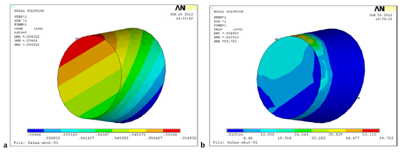
Dentine abutment showed maximum Von Mises stress lower values than those of Ti abutment by about 29.5 % under both vertical and oblique loads. On the other hand it showed higher total deformation than Ti abutment by 54.5 % and 33.3 % under vertical and oblique load, respectively, as presented in Figure 6. Ti implant showed worse performance than natural root. It transferred higher stress to underlying spongy bone denoting lower susceptibility of osseointegration around Ti implant. Samples of Ti implant results under layered ZrO2 crown that subjected to oblique load are presented in Figure 7.
Cortical and spongy bones behavior was illustrated in Figure 8 and 9 as distributions of deformation and different stress types. Spongy bone showed higher value of maximum Von Mises stress in case of Ti implant than dental root in case of FMZ and under both vertical and oblique loads.
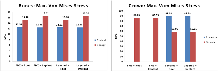
The two substructure results both crown types (FMZ, and layered ZrO2 crown) had negligible effect on either Ti implant or dentine root or on two types of bone as presented in Figure 10. Which contain a graphical comparison of maximum Von Mises stress, on bones and crown under vertical load.
All parts of the model are safe under such loading conditions. Vertical loading is more critical from mechanical point of view specially that its value is about double the oblique one. Zirconia has showed higher stability and durability in comparison to other ceramic materials used as frameworks. While the major problem accompanied with ZrO2 framework is the chipping of porcelain veneer.31 That may be precipitated due to difference in CTE between core and veneer material, surface finish of core material causing flaws and defects which, yield residual stresses at the interface or due to wettability of the veneer material and its volumetric shrinkage properties.32 Not much research were done on FEA of monolithic ZrO2 till now but by analyzing the results of this study it was found that maximum Von Mises stress resulted in FMZ crown are within the safe levels (86.05 MPa) that far away below the fatigue limit of colored Y-TZP type (600 MPa) used in this study.33 In contrast with the results of a previous study,34 where the difference in young’s modulus between ZrO2 and Porcelain affected Von Mises stress resulted within cement layer, the present study showed no significant difference in maximum Von Mises stress values within the cement layer under both types of crowns. That may be attributed to the fact that cement had the lowest elastic modulus value that in turn had led to higher energy absorbance by this weak layer by almost the same amount. On the other hand porcelain veneer had significantly reduced the principal stresses by about 30 % than it was in case of FMZ. This finding support the theory that porcelain veneer has protected the core by reducing the stresses or energy transferred to it (31). Although stresses are safe for both FM and core ZrO2 but the fact that the flexural strength of core ZrO2 is higher than that of FMZ material35 puts the material with lower flexural strength under higher Von Mises stress and vice versa. That point concerned with material durability needs more research. In agreement with a previous study31 the lower elastic modulus value for porcelain veneer resulted in lower energy transferred to the ZrO2 core in which the maximum Von Mises stress and principal shear stress were concentrated on the occlusal surface below the applied force in the interface region. Although, the maximum Von Mises stress may exceed the values of ceramic veneers chipping shear stress (31 – 38 MPa),36 it is not dangerous for the bond between core and veneer materials under applied compressive loads. That, the coating layer stress state, is dominated by compressive stress, while shear stress did not exceed 30 MPa. Monolithic ZrO2 crown has the advantage of absence of this veneer coating thus eliminating that risk of chipping failure. In general layered crown may absorb more energy than FMZ crown, therefore it may be recommended over the FMZ one for two reasons first porcelain veneer may protect the underplaying core and second it is supposed to transfer lower energy to the underlying cement phase.
Titanium implant has more rigid properties than bone material resulting in unresolved compatibility between the two structures and the modified active coating is easily lost during implant process.37 In agreement with previous study, material (dental root) with lower elastic modulus resulted in lower energy or stresses transferred to surrounding spongy bone by 29.5 % than material with higher elastic modulus (Ti implant).38,39 This may be attributed to higher stiffness of Ti implant that resulted in higher stress transfer to surrounding bone and thus impaired durability of the implant material resulted from higher possibility of future bone resorption under applied vertical or oblique loads. The high Ti implant elasticity may produce significantly higher spongy bone deformation under vertical load by 75 % higher than the case with dental root. Von Mises stress values on both types of bones are accepted and ensured safe lifetime functioning. Both cases showed safe and acceptable values and no worry from fatigue failure on these parts.
Oblique loading in this study generates stresses of order 30% of the vertical load cases at the top (outer) layer of the crown. The inner part (core) of the crown showed the same trend and order of magnitude for different types of stresses and deformations. These results were easily expected from the load value and oblique angle under linear analysis.
Spongy bone suffers from higher stresses under implant (Titanium root) by about 8.8%, that Titanium is stiffer (or more rigid) than dentine root. That is why it may transfer more energy to the spongy bone than the dental root. While spongy bone showed higher deformation of about 1.0 to 1.5 microns under dental root than it did under the Ti implant.
Cortical bone is safe in all cases included in this study. About only 0.65% maximum difference between stresses generated on cortical bone under both types of crowns and both types of infra-structure complexes was detected.
Dentine Root (natural root) receive less stresses than titanium implant by about 36% that it matches bone(s) properties. Lower deformation in Ti implant, in comparison to natural root helps in fast osseointegration.
Cement of 50 µm layer thickness is safe in all cases included in this study. Dentine root is better than implant (Titanium root) that reduces generated stresses, but deformations showed the opposite trend. Both types of crowns showed insignificant difference on stresses generated on the cement layer and root.
Crown made from single material (Zirconia) is stiffer than ZrO2 core with porcelain veneer. Therefore the crown outer layer receives more energy and stresses (of order 3.8%) if it was manufactured from less rigid material than Zirconia like Porcelain. That the crown core (inner part) will receive less stresses (about 38%) and energy if it was coated by Porcelain (softer than Zirconia).
Coating Material (Porcelain) deforms about 1 micron more than the same layer if it was made from Zirconia (as the crown core material). This deformation is indicative for more energy absorption. This as a general rule using softer crown coating material is preferred to reduce energy and stresses transfer to the underneath parts.
Generally, Porcelain veneer had higher deformation than FMZ surface and transferred lower energy to core substructure. Thus, layered crown may have higher probability to veneer chipping, hence, a probability to failure under maximum occlusal loading which is rarely occurred.
None.
The author declares that there is no conflict of interest.

©2014 Fathy, et al. This is an open access article distributed under the terms of the, which permits unrestricted use, distribution, and build upon your work non-commercially.