Journal of
eISSN: 2373-4345


Case Report Volume 3 Issue 2
2Private practitioner in Dubai, UAE
2Dental surgeon, France
3Denturist, CERAMCAD laboratory, France
Correspondence: Philippe Tardieu, Private practitioner in Dubai, UAE
Received: June 03, 2015 | Published: November 19, 2015
Citation: Tardieu P, Coste BC, Garampon D. Implant-supported, fiber-reinforced bridge: from guided surgery to immediate loading. J Dent Health Oral Disord Ther. 2015;3(2):279-285. DOI: 10.15406/jdhodt.2015.03.00085
For several years, the patient, aged 76 years and presenting no medical contraindications to implantation, has been wearing a screw-retained, implant-supported bridge on the lower jaw; with fiber reinforcements of the Fiber Force® CST (Cable Stayed Technology) type instead of the standard practice rigid metal bars
Keywords: immediate loading, implant-supported bridge, guided surgery, digital planning, passive fit adjustment, impression technique
For several years, the patient, aged 76 years and presenting no medical contraindications to implantation, has been wearing a screw-retained, implant-supported bridge on the lower jaw; with fiber reinforcements of the Fiber Force® CST (Cable Stayed Technology) type instead of the standard practice rigid metal bars (Figure A-E).
This approach is a fundamental deviation from usual practice.
A three-dimensional fiber structure was built on the jaw (visible by transparency on the panoramic x-ray), with injection or pressure insertedmethacrylate resin to form a high resistance fiber-reinforced resin compound. The fibrous structure is solidly secured to the implant connections.
The patient refuses long and complex treatment involving bone grafts on the upper jaw, and her financial means are limited. It was decided to insert 6 implants with early loading of a fiber-reinforced resin bridge, of the same type as that on the lower jaw.
Preparation was carried out using the AccuGuide® program, selected for its user-friendliness and precision.
Command of the guide, file exchanges and communication are managed on-line in interactive mode, and the surgeon can delegate all or part of the case to a specialized team while controlling and validating every step, which is a huge advantage in terms of case management. The entire process, from data transmission to reception of the guide, can be completed in less than 7days (Figure 1).
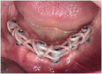
Figure B Clinical photo showing the positioning of the fiber reinforcements around the implant posts.
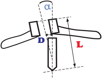
Figure 1 The AccuGuide® program is characterized by 3° axial deviation (a), 0.3mm deviation at the point of entry (D) and 0.4mm for drilling length (L).
The imaging work is carried out in four steps:
The first three steps are purely digital before actual production of the guide using a 3D printer.
At this stage, a density threshold must be defined, above which all the voxelswill be integrated in the 3D image: this is segmentation. Determining the reconstruction threshold (Hounsfield units, HU) is a key element of segmentation. The higher the threshold, the fewer the elements included in the volume; the lower the threshold, the more elements included in the volume. Operator experience and diligence play a vital role in the results obtained by 3D printing.
After segmentation of the teeth and cleaning of the bone, an implant plan is proposed according to the practitioner's indications and sent for correction or validation. (Figure 2) Implant planning after bone cleaning and virtual extraction of the remaining teeth.
(Figure 3) The U Plan module is used to validate implantation: it is possible to alter the length, diameter and spatial position of the implants, and even change brands, at any time. This aspect of the software enables the practitioner to plan the implantation according to his own clinical experience.
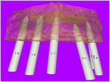
Figure 3 The U Plan module is used to validate implantation: It is possible to alter the length, diameter and spatial position of the implants, and even change brands, at any time. This aspect of the software enables the practitioner to plan the implantation according to his own clinical experience.
U Design Module
The U Design module enables design of the surgical guides. Design is automatic for two types of guide: One Shot and Spoon. However, all kinds of guides, for all makes, can be designed to measure by setting the guide design parameters. ANPA MEDICAL SUPPLIES DMCC was entrusted with this phase. A bone support Spoon guide was designed for this clinical case. The company then exported the guide design in STL format and published the surgical form. The guide design can be validated by the practitioner before printing if required (Figure 4-6).
Guide Production
A Smart Guide, whose function is limited to guiding the pilot drill, was selected for this case. The next sequences were carried out freehand, leaving the practitioner free to practice his specialization and make his own decisions. It is extremely useful to be able to adapt the surgical act to the tactile sensations and the inevitable random events related to surgery. The guide was produced using a 3D printer (3D System) in a certified UniGuide Dental center. Guides are made from USP type class VI bio-compatible resin according to very strict protocols. The guide is delivered with a roadmap for the surgery, indicating the position, implant reference and length of guide drill to be used. The reliability of the guide ensures much appreciated surgical precision but still leaves the practitioner free to make his own decisions.1-3
The early loading decision is taken based on the results of the AccuGuide® programming and the clinical data. The implants are inserted into type 2 and 3 bone (Hounsfield units > 400) and the final tightening torque was always above 45 Ncm.
These data, the only data accessible to the clinician, are those retained by Esposito et al.4 in a study published in 2009, classed as best evidence by Cochrane Library, which states "it seems that immediate loading fails less often than conventional loading and that immediate loading is therefore preferred to waiting 1 or 2 months" (Figure 7-8).
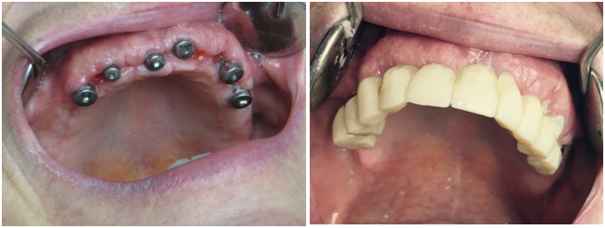
Figure 7,8 A reinforced acrylic bridge with a hybrid glass-acrylic braid enabled early loading on the healing abutments.
(Figure 9 & 10) After 10 days soft tissue healing and inspection of implant stability, the MUA posts (multi-unit abutment) and their multi-unit super-structure were installed.
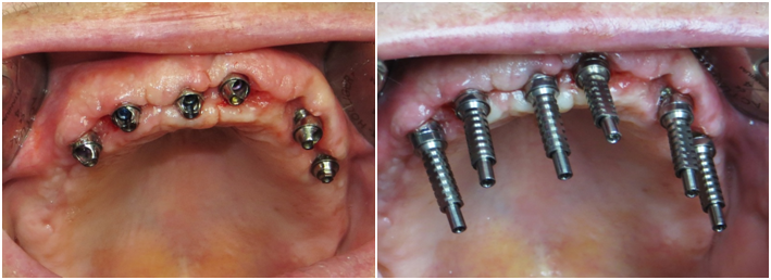
Figure 9,10 After 10 days soft tissue healing and inspection of implant stability, the MUA posts (multi-unit abutment) and their multi-unit super-structure were installed.
For immediate loading, the first decision criterion is absolute passivity of the implant prosthesis on the implants, to obtain a non-pathological level of bone deformation (variable depending on the type of bone5), enabling the strain suffered by the bone to remain constantly below the threshold of irreversible micro-damage; permanent strain on the posts due to an unsuitable rigid framework would obviously cause irreversible damage.
The passivity of this framework is only possible if the model sent to the lab technician is an exact representation of the clinical situation. The CST Link® system enables rapid and precise recording of the spatial positioning of the implant posts (Figure 11).
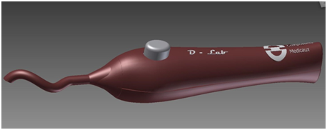
Figure 11 A braid of hybrid glass-resin CST Link® that can be polymerized under blue light contained in a gripper-tension tool (CST Tool) enables distribution according to a protocol based on winding around the implant posts.
The CST Link® hybrid braid is composed of an external sheath of woven glass threads containing glass threads arranged lengthwise. These threads are composed of an assembly of 9µm long glass fibers with good structural dimensional stability. (Figure 12) The resin impregnated in each fiber of each thread represents 6% of the mass and therefore its contraction after polymerization remains extremely slight and undetectable (less than 0.06%).6
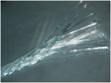
Figure 12 The resin impregnated in each fiber of each thread represents 6% of the mass and therefore its contraction after polymerization remains extremely slight and undetectable (less than 0.06%).
Spatial stability tests were carried out on a CST Link® type fiber-reinforced structure, coated with translucent silicone and polymerized on four posts, using a profile projector and doubled with 3D camera measurements: an average deviation of gap of 0.07% (between posts 1 and 3) were observed, which correspond to a gap of 19µm. Plaster control keys, built on a model replica, remained free of fractures and cracks, demonstrating the perfect passivity of the structures (Figure 13-15).7
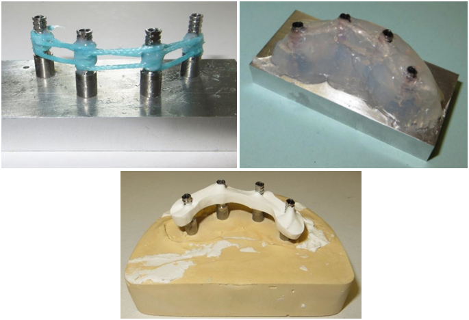
Figure 13-15 Spatial stability tests were carried out on a CST Link® type fiber-reinforced structure, coated with translucent silicone and polymerized on four posts, using a profile projector and doubled with 3D camera measurements: an average deviation of gap of 0.07% (between posts 1 and 3) were observed, which correspond to a gap of 19µm. Plaster control keys, built on a model replica, remained free of fractures and cracks, demonstrating the perfect passivity of the structures.
A braid of CST Link® is held in place with clamp forceps, placed behind the most distal implant post and wrapped around it once. The braid is quickly secured locally by rapid photo-polymerization under blue light (Figure 16). The CST Link® braid is then continued and looped counter-clockwise aroundeach post, towards the left most distal post. It is held tight using the D Lab tool (Figure 17).
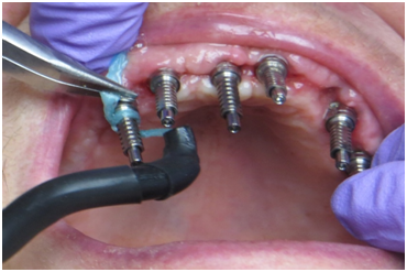
Figure 16 A braid of CST Link® is held in place with clamp forceps, placed behind the most distal implant post and wrapped around it once. The braid is quickly secured locally by rapid photo-polymerization under blue light.
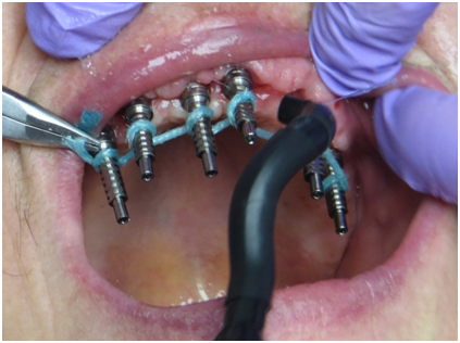
Figure 17 The CST Link® braid is then continued and looped counter-clockwise around each post, towards the left most distal post. It is held tight using the D Lab tool.
The braid thread is looped around the left post and a second passage is made, maintaining tension, towards the right post (Figure 18). Having looped around the right distal post, movewards the left distal post (Figure 19). The final passage ends with a loop around the most distal left post. The whole assembly is photo-polymerized (Figure 20). This forms a framework with three offset layers, solidly secured to the implant posts.
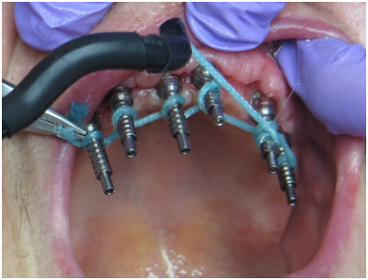
Figure 18 The braid thread is looped around the left post and a second passage is made, maintaining tension, towards the right post.
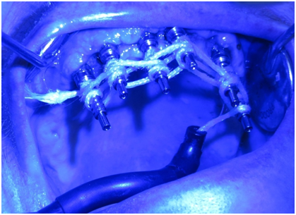
Figure 20 The final passage ends with a loop around the most distal left post. The whole assembly is photo-polymerized. This forms a framework with three offset layers, solidly secured to the implant posts.
Blue Fiber Force® photo-polymerizable resin is deposited onto each post, securing the 3D framework definitively to the posts and preventing any axial displacement or rotation (Figure 21 & 22).
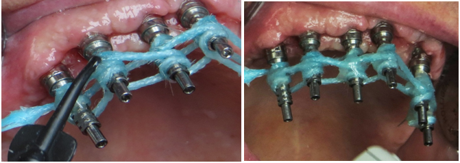
Figure 21,22 Blue Fiber Force® photo-polymerizable resin is deposited onto each post, securing the 3D framework definitively to the posts and preventing any axial displacement or rotation.
Translucent silicone (Fast Splint MATRIX®) is injected around the posts (Figure 23 & 24). A membrane impression tray is filled with the same silicone and inserted around the prepared structure. The membrane enables the material to be compacted to make an impression of the soft tissues. An open impression tray would not enable this compacting to allow recording of the contours of the soft tissues. While the silicone sets, polymerization is completed through the translucent material (Figure 25).
After unscrewing the MUA post screws, facilitated by the direct view of the screw heads through the translucent silicone, the impression is removed and the post replicas are screwed onto the impression transfers. The laboratory model is cast and the MUA posts are screwed into place and sanded / silanized (Figure 26-28).
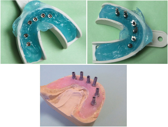
Figure 26-28 After unscrewing the MUA post screws, facilitated by the direct view of the screw heads through the translucent silicone, the impression is removed and the post replicas are screwed onto the impression transfers. The laboratory model is cast and the MUA posts are screwed into place and sanded/silanized.
From the aesthetic assembly, the prosthetic implant is made according to the Fiber Force® CST technique. A very high resistance implant supported fiber-reinforced resin bridge is then produced, affording a perfect passive fit in terms of its mechanical effect on the implants and their accessories (adaptation without tension) and its interference with the play of the mandibular or maxillary bone parts. The impression technique makes the plaster validation key test unnecessary. However, the test was carried out in this case for demonstration purposes. Our experiment revealed that the plaster key screwed onto the implants never breaks (Figure 29-31).
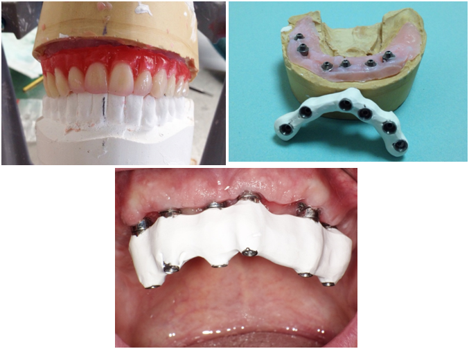
Figure 29-31 From the aesthetic assembly, the prosthetic implant is made according to the Fiber Force® CST technique.
The three-dimensional fiber-reinforced structure is built up simply using photo-polymerizable glass fiber braids bonded onto the implant posts and injection-coated with methacrylate resin. The final assembly thus forms a self-supporting structure ensuring stability simply by the rigidity of its shape (Figure 32). The local prosthetic laboratory processes the wax model and proceeds with PMMA resin injection to make the Fiber Force® CST bridge using conventional techniques (Figure 33 & 34).
The injection or pressure molded prosthesis can then be inserted passively onto the MUA posts. This can generally be done in one day (Figure 35-37). The prosthetic screws are naturally inserted with no tension, thus validating the exceptional adaptation of the structures. They are tightened as per manufacturer instructions (Figure 38 & 39).
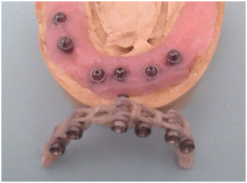
Figure 32 The three-dimensional fiber-reinforced structure is built up simply using photo-polymerizable glass fiber braids bonded onto the implant posts and injection-coated with methacrylate resin.
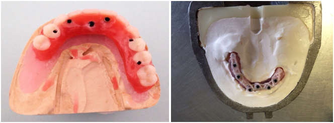
Figure 33,34 The local prosthetic laboratory processes the wax model and proceeds with PMMA resin injection to make the Fiber Force® CST bridge using conventional techniques.
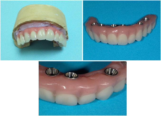
Figure 35-37 The injection or pressure molded prosthesis can then be inserted passively onto the MUA posts. This can generally be done in one day.
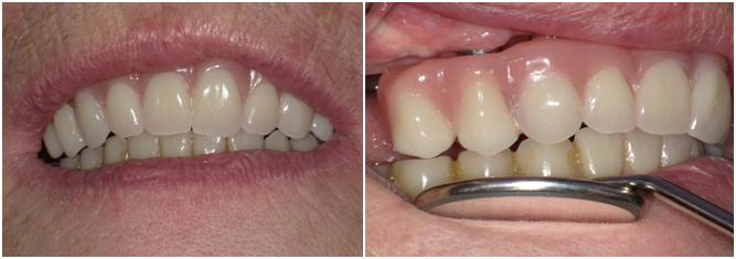
Figure 38-39 The prosthetic screws are naturally inserted with no tension, thus validating the exceptional adaptation of the structures.
Osseointegration occurs when micromotion is between 50 and 150µm8 but is this motion truly quantifiable between these two values with a rigid metal connection in a context of complex deformation of bone parts related to the type of bone and the geometry of the bone parts? Has it been proved that excessive rigidity is not actually harmful in this fluctuating context (dentistry based on proof)?
It is often suggested that a rigid connection would enable better distribution of strain over the implants. However, the word "distribution" is ambiguous: each implant would be under stress from different forces and dependent on the point of application of the force. Furthermore, the amount of effort on each implant would depend on the section of the rigid metal bar (modulus of inertia of the section). In the case of effort on a distal extension, the adjacent implant would be "stamped" on the bone and serve as a "pivot" and the other implants would be under extraction strain by swinging of the bar around the pivot implant.
Mechanically, the bars would not, depending on their profile (some are tall and narrow with a high modulus of inertia - the height has a huge effect), bend or only slightly, but the force on the most distal implant would be the same as for a more flexible CST framework.
However, it can be said that the application of forces would be instant in the case of a rigid system and damped by the visco-elastic system of CST: the overlapping of the braids can be likened to a system of springs (a fiber-reinforced compound cannot suffer permanent deformation) since the resin acts as a shock absorber and the assembly as a whole absorbs the strain (dashpot).

©2015 Tardieu, et al. This is an open access article distributed under the terms of the, which permits unrestricted use, distribution, and build upon your work non-commercially.