Journal of
eISSN: 2373-4345


Research Article Volume 1 Issue 2
1Department of Orthodontics, Faculty of Dentistry, University of Aleppo, Syria
2Department of Aeronautical Engineering, Faculty of Mechanical Engineering, University of Aleppo, Syria
Correspondence: Mahmoud AL-Suleiman, Department of Orthodontics, Faculty of Dentistry, University of Aleppo, Aleppo, Syria, Tel 967000000000
Received: May 09, 2014 | Published: May 30, 2014
Citation: Suleiman MAL, Baba F, Suliman A, et al. Clinical evaluation of upper incisors retraction frictionless system depending on mini-screw. J Dent Health Oral Disord Ther. 2014;1(2):30-37. DOI: 10.15406/jdhodt.2014.01.00009
Objectives: The aim of the study was a computed and clinical evaluation of upper incisors frictionless retraction system using mini implants.
Methods: Three dimensions mechanical analysis has been done by Software for model geometry ((Anasys ver. 11)). The retraction system consisted of mini implant as a point of support and a rigid orthodontic arch wire for the anterior teeth stabilization that extended 2mm distally and 6 mm gingivally from bracket’s slot to formed Power arm as a point to apply the retraction force. The two models of springs that had been made of TMA and Elgiloy Alloys, as a source of the orthodontics force had been used. The results of finite elements analysis were applied at 27 class II division 1 malocclusion patients (13male, 14female). The patients divided into two groups. Applying a triangle spring at group one with 4 mm activation and applying a circle spring at group two with 2mm activation.
Results: The movement in group 1 was the partly Controlled tipping by translation with the ratio of the apex movement to edge movement (0.38±0.42), but in group 2 the movement was the controlled tipping by translation with relation (0.69±0.51) and no significant difference was between groups (p=0.93).
Conclusion: The suggested frictionless retraction system produced good control of the upper incisor movement.
Recent researches carried out to avoid the complications of incisors’ retraction by conventional techniques such as losing of the anchorage, control torquing and no bodily movement.1−4 Absolute anchorage can be achieved by using orthodontic implants.5 The Mini–screws were used for incisors retraction without losing anchorage in comparison to the traditional method retraction6,7 and the optimal treatment can complete without patient’s cooperation, and without anchorage losing.6,8,9 The control of the orthodontic movement depends on the relationship between force vector and the center of resistance. When the force vector passes through the center of resistance, the movement should be bodily, However, and will be tipping when it does not pass through the center of resistance, that affected by force magnitude and distance between force vector and the center of resistance.3,10 The centers of resistance of central incisor and lateral incisor were 9.6, 8.6 mm from bracket`s slot respectively.11,12 In other studies of four upper incisors was 77% from the apex of root13 and 5mm gingivally form alveolar crest14 and was at 7mm gingivally from center alveolar crest for all anterior teeth, or 9-10mm gingivally and 7mm distally from the center of the lateral incisor bracket.15,16 Power Arm’s length affects on controlling the incisors retraction movement, when mini-screw used as supporting point. If arm length increased, torque movement increased and intrusion movement decreased.17 8-10mm height recommended for torque movement and 6-8mm for tipping controlled movement.18
Moments and reaction of mechanical system can canceled by one couple system, that is practical application of determinate force system as cantilever spring, and moments stay constant. Consequently, no friction, 3D movement control, safe time and efforts will be gained.4,9,20 Park et al.21 used positioners for retain the teeth and lever arm for force application, they concluded that frictionless retraction was benefit for movement control.
Updhyay et al.22 found that incisors retraction by skeletal anchorage was more speed than incisors retraction by traditional anchorage. Choy et al.23 used statically determinate frictionless retraction system for upper incisors retraction; they concluded that there was no extrusion or tipping movement. Park et al.24 used segmental retraction; they observed that the force vector passed through resistance center that resulted in a controlled movement.
Objectives
The aims of this study were a clinical evaluation of computerized designed system for upper incisors frictionless retraction depending on mini-screw.
The retraction system consisted of:
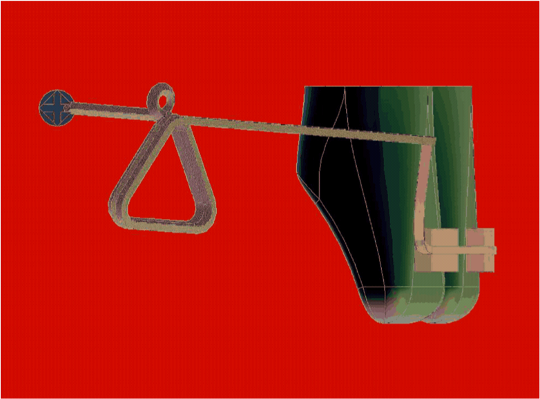
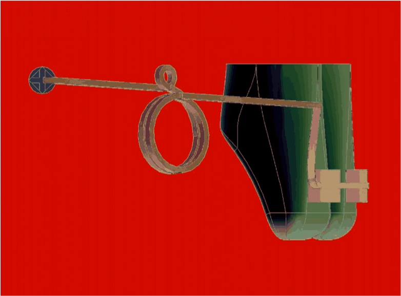
Mini-screw was the support point. A rigid orthodontic arch wire used for the anterior teeth stabilization; that extended 2mm distally, and 6-8 mm gingivally to form a Power arm that considered as a point of force application. Self drilling mini-screw of Titanium Alloy (Ti6AL4V) (Forestadent- Germany), 9mm length, 1.6mm diameter, 2mm neck (Cross head & Cross hole #0.8mm) used, that inserted at 8mm above main wire between first molar and second premolar in mucogingival junction under (after initial leveling and aligning) according to Sung.25,26
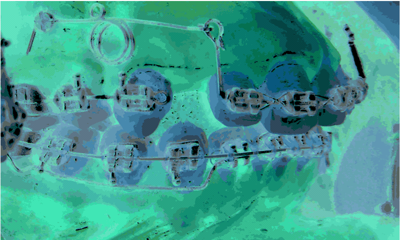
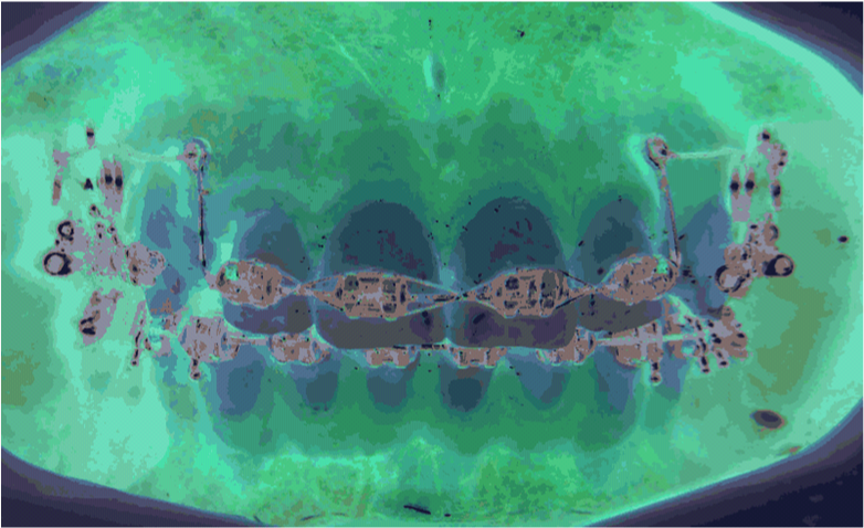
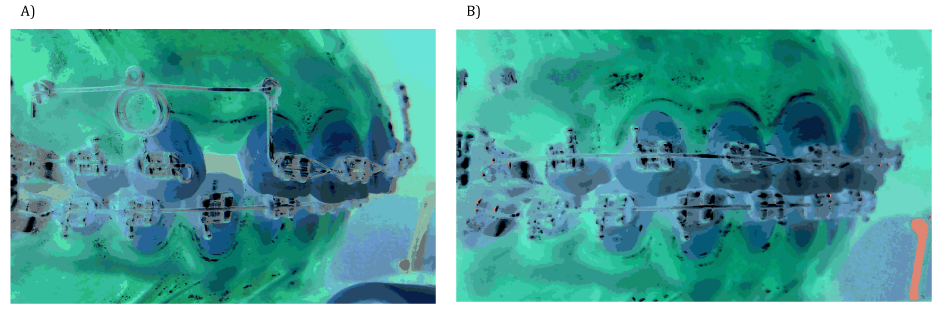
Two models of spring created as the source of forces that extended from mini-screw to a power arm. Every model was made of TMA and Elgiloy alloys; the first: a Triangle loop, with the inner side length was 5mm, 0.016*0.022 Inch cross section (Figure 1) and the second: a circle loop, with the diameter was 5mm too; 0.016*0.022 Inch crosses section (Figure 2). Software for model geometry ((Anasys version 11)) was used for three dimensions mechanical analysis to determine the optimal form of the springs according to the load/ deflection rate. Orthodontic Bands (0.018 inch) (RMO), Pre adjusted appliance Brackets (0.018 Inch) from (Forestadent- Germany) applied. 0.016×0.022 Inch TMA wire, 0.016×0.022 Inch Elgiloy Blue wire (RMO) and 0.018* 0.025Inch, SS arch (Universal form) (IOS- USA) were used (Figure 3 & 4).
The conclusion of finite elements analysis of springs, were applied at 27 patients (13 male, 14 female), who had class II division 1 malocclusion and the upper first premolar extracted, which required maximum anchorage for upper incisors retraction (Table 1). All the participated patients signed a consent form and approved the follow up of treatment, and then Subjects randomly divided into two groups. TPA and 0.016*0.022Inch cross section SS wire used for stability of posterior segments. 100 g of force applied on each side, the springs were activated every 40 days. Retraction stopped when overjet (2.5-3mm) had achieved.
|
Patient |
Age |
Overjet |
Spring |
Activation |
Load- deflection Rate |
Group 1 |
14 (7male-7female) |
19.1 ±2.1 |
7.2 ±1.4mm |
Triangle (TMA Alloy) |
4mm |
26.315g |
Group 2 |
13 (7male-6female) |
19.4 ±3.8 |
7.5 ±1.7mm |
Circle (TMA Alloy) |
2mm |
47.504 |
Table 1 Description of sample
Lateral cephalometric radiographs carried out at three times, T0 before retraction, T1 after two months of retraction and T2 after finishing. The reference lines, used to evaluate the changes in position of Upper incisors, were the SpP line as the x-axis, and the line perpendicular to it through Ptm (pterygomaxillary point) as the y-axis, These reference lines used for local superimposition between two times of retraction.
Evaluation retraction movement carried out by:
Edge I/X(mm) & Apex I/X(mm) |
Vertical movement of central incisors |
Edge I/Y(mm) & Apex I/Y(mm) |
Horizontal movement of central incisors |
I/SpP(θ) |
Angle of central incisors axis and SpP plane |
Over jet (mm) |
Distance between baccul of lower & upper incisor |
Table 2 Variable of incisors retraction
15% cephalometric radiographs of three stages (T0, T1, and T2) were randomly selected to return the measurements by one examiner twice at, a 4-week interval and another examiner and Cronbach’s Alpha was used for Reliability. The data analyzed by SPSS 17 Using independent sample. (T-test) to compare between two groups, Paired sample (T–Test) to compare treatment changes in group 1 & 2 after emphasized the standard distributed of parameters by Anderson- Darling test.
Finite element study
The load/ deflection rate of Elgiloy alloy spring was bigger than TMA alloy spring and had reverse correlation with Length of wire, (One loop, Double loop, and double loop-one helix). 8mm height of Power arm was the better to reach the translation movement (Table 3). Moreover, concluded that:
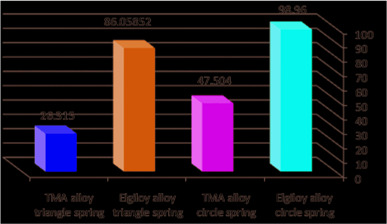
Evaluation of Produced Moment at Incisors (Mf, Mc, Mv, Mc/F) |
|||||||||
|---|---|---|---|---|---|---|---|---|---|
6 mm Power Arm Height with Differential 2 mm between Power Arm and Miniscrew |
|||||||||
MN-Mf |
MN/Mf Ratio |
MN/Fz Ratio |
MN=(Mc+Mv) |
Mv |
Mc(Fd*8) |
Mf(Fd*2) |
Fz(H) |
Fy(V) |
F(g) |
241.19 |
1.69 |
6.78 |
587.6 |
68. |
519.61 |
346.41 |
86.60 |
9.71 |
100 |
7 mm Power Arm Height with Differential 1 mm between Power Arm and Miniscrew |
|||||||||
365.02 |
2.40 |
7.2 |
625.63 |
17.528 |
608.11 |
260.619 |
86.873 |
2.504 |
100 |
8 mm Power Arm Height with Differential 0 mm between Power Arm and Miniscrew |
|||||||||
523.69 |
4 |
8 |
698.25 |
0 |
698.25 |
174.56 |
87.281 |
0 |
100 |
Table 3 Resulted of FEM at incisors
T0-T2 |
Group 1 (Triangle Spring) |
Group 2 (Circle Spring) |
t-Test Independent |
|||
|---|---|---|---|---|---|---|
Mean |
S.D |
Mean |
S.D |
Sig Value |
||
Apex I/Y(mm) |
1.7 |
1.6 |
2.4 |
1.1 |
0.55 |
NS |
Edge I/Y(mm) |
4.9 |
2.3 |
4.6 |
1.9 |
0.27 |
NS |
Apex I/X(mm) |
-0.39 |
2.59 |
0.53 |
1.37 |
0.43 |
NS |
Edge I/X(mm) |
0.25 |
1.8 |
0.69 |
1.1 |
0.14 |
NS |
I\SpP(θ) |
-6.71 |
5.9 |
-4.34 |
5.6 |
0.71 |
NS |
Table 4 Mean of vertical, horizontal and axis movement
Stage (T0-T2) |
Stage (T0-T1) |
Group 2 |
Stage (T0-T2) |
Stage (T0-T1) |
Group 1 |
-2 |
0 |
1 |
0 |
0 |
1 |
+6 |
+73 |
2 |
∞ |
∞ |
2 |
+50 |
∞ |
3 |
-2 |
-3 |
3 |
+11.5 |
+21 |
4 |
+2 |
+12 |
4 |
+24.5 |
+77 |
5 |
+6 |
+1.5 |
5 |
+19 |
+36 |
6 |
-3 |
0 |
6 |
+77 |
+46 |
7 |
∞ |
∞ |
7 |
-23.5 |
∞ |
8 |
-24 |
-56 |
8 |
∞ |
∞ |
9 |
+6 |
∞ |
9 |
+4 |
+4 |
10 |
+13 |
+29 |
10 |
∞ |
-46 |
11 |
+19 |
+55 |
11 |
-99 |
-43 |
12 |
-4.5 |
-3 |
12 |
+52 |
∞ |
13 |
-7.5 |
+67 |
13 |
|
|
|
+21 |
+20 |
14 |
Table 5 Values of rotation center.
Results of clinical study
The reliability mean of viability was 0.964 in (T0, T1, and T2). The speed of retraction of group1and group 2 was 1.03±0.32mm/mo, 0.842±0.169 mm/mo respectively and no significant difference was between groups, p=0.076. No significant difference was between two group’s means of apex and edge of upper incisors movement (Table 4).
The center of Rotation (Cr.O)
Multi values of location of the center of rotation were between negative, positive and infinite values in both groups at stage (T0-T1) & (T0-T2) (Table 5, Figure 7). No significant difference was between groups at stage (T0-T1) and stage (T0-T2); Significant difference was between stages (T0T1) & (T0T2) in each group (Table 6, Figure 8).
|
Groups |
N |
Mean |
SD |
SE |
t-Test of Means Independent Sample |
|
Sig Value |
|||||||
Center Rotation |
Triangle Spring |
14 |
31.89 |
50.23 |
13.42 |
.403 |
NS. |
Circle Spring |
13 |
50.15 |
61.20 |
16.97 |
|||
Center Rotation |
Triangle Spring |
14 |
7.50 |
15.12 |
4.041 |
.222 |
NS. |
Circle Spring |
13 |
28.11 |
59.59 |
16.52 |
|||
Paired Samples Test |
Sig |
.044 |
|
||||
Table 6 Rotation of center of groups
Type of movement
Different types of movement were recorded between groups in both stages (T0-T1) and (T0-T2) according to proposed formula (Uncontrolled tipping, Controlled tipping, Controlled tipping to bodily, Bodily and Torque movement) (Figure 9, Figure 10). Partly controlled tipping by translation of the apex movement to edge movement ratio was for group1, controlled tipping to translation was for group2 and no significant different was between groups in both stages (T0-T1) and (T0-T2): p=0.111, p=0.93. No significant difference was between stages (T0-T1) and (T0-T2) in both groups (Figure 11, Table 7).
|
Group |
N |
Mean |
SD |
SE |
t-test for Equality of Means Independent Sample |
|
Apex.M(T0-T1)\ Edge.M(T0-T1) |
Triangle Spring |
14 |
.390 |
.864 |
.230 |
Controlled tipping partly by translation |
N S.111 |
Circle Spring |
13 |
.857 |
.562 |
.155 |
controlled tipping to translation |
||
Apex.M(T0-T2)\ Edge.M(T0-T2) |
Triangle Spring |
14 |
.380 |
.428 |
.114 |
Controlled tipping partly by translation |
N S |
Circle Spring |
13 |
.697 |
.514 |
.142 |
controlled tipping to translation |
||
Paired Samples Test (T0-T1) - (T0-T2) |
N S. |
.475 |
|
||||
Table 7 Type of movement of groups
Finite element study
Manhartsberger et al.28 suggest low load deflection Rate of spring for control of movement. Load deflection rate affected by wire length as loops, helixes and affected with memory alloys.1 The springs consisted of TMA alloy double loop–one helix had low load–deflection rate for two models.2 Load-deflection rate of TMA alloy was 26.315g/mm and 47.504g/mm, for triangle and Circle forms respectively. Both of springs were considered lower than load-deflection rate of PG spring (100g/mm), T loop (55g/mm), vertical loop (114g/mm), double vertical loop (75g/mm).29 The optimal force of incisors’ retraction is 100g/cm.6,30 Therefore, the activation amount of TMA alloy triangle spring is 4mm, TMA alloy Circle spring is 2mm (Table 1). Mc/F=8 ratios will be achieved when power arm length was 8 mm comparison with 6-7mm which gave Mc/F ratio (6.7-7.2) (control tipping movement) according to FE analysis despite the vertical moment was added to a couple moment.12,15,16
Clinical study
In recommended system, the force vector applied at 8mm above bracket’s slot that produced a horizontal movement of edge and apex of upper incisors for group14.9±2.3mm, 1.7±1.6mm respectively, and 4.6±1.9mm, 2.4±1.1mm for group2 respectively. No significant difference was between groups. The speed of upper incisors retraction at group1 was better than group2. Maybe the reason is the deactivation of springs; the deactivation of triangle spring after 1mm movement is 26.3 g/mm, and the remained force is 78g, which can move the incisors. While the deactivation of the circle spring after 1mm movement is 47.5g/mm and the remained force is 47.5g which is not suitable to move the incisors. Comparing to Dincer’s results, when he applied 150g at 9mm for upper incisors retraction, and had noticed horizontal movement of root and edge 0.21±0.19mm, 3.45±0.41mm respectively (Figure 12).27

No extrusion movement of upper incisors (Table 4) resulted by paralleling the force vector to the main wire,31 in addition, the recommended system is the practical application of determinate force system which can easily discern, measure and evaluate the moments and force.23 The axis of upper incisors had changed about -6.71±5.9 degree for group 1, -4.34±5.6 degree for group 2, and no significant different was between groups p>0.05 (Table 3).
The center of Rotation
The translation movement has achieved when the center of rotation is at infinity.32 Siatkowski11 demonstrated that the translation movement can be achieved by both inclination of incisors 58° at Op, and Mc/F=8mm ratio. FE analysis of recommended system showed that 8mm power arm height achieved Mc/f=8mm, and the inclination of incisors of group1 (triangle spring) was 61.7°±5.0° and 62.7°±4.2° in Group 2 (circle spring) (Figure 13).
The results showed that center of rotation was at 31.8±50.2, 50.1±61.2 Group 1 & Group 2 respectively for stage one (T0-T1) and no significant difference was between groups P=0.403.
Various positions of the center of rotation were in every group (infinity, positive and negative values). According to Manhartsberger et al.28 & Turk et al.33 the reasons maybe were the individual difference between patients such as root length, alveolar bone, initially inclination of incisors and PDL morphology. The results of the rotation center were 7.5±15.1, 28.1±59.5 at Group 1 & Group 2 for retraction stage (T0-T2). No different significant was between groups p=.222. Fallback of center rotation could be resulted because the limiting factors in orthodontic retraction such as palatal cortical bone and width of alveolar bone,33 or the retraction distance.34
Type of Movement
Jung and Kim35 recommend 10mm power arm height to produce the controlling movement retraction. Sia et al.18 recommended 8-10mm power arm height to achieve torque movement, 6-8mm power arm height to have controlled tipping movement.
Applying force at 8mm power arm height produced equivalent moment 523g.mm, force moment 174g.mm and force at root apex 65.3g according to finite element analysis of recommended system. Using the formula of the apex movement to edge movement ratio, movement type of group 1 was uncontrolled, controlled tipping to bodily movement (0.39±086), beyond in group 2 was controlled tipping to bodily movement (0.85±0.56) during two months of retraction (T0-T1). No significant difference was between groups p=0.111. The ratio of the completed period of retraction (T0-T2) in group 1 and group 2 were 0.38±0.42 and 0.69±0.51, respectively (controlled tipping to bodily movement), no significant difference was between groups p=0.093. Upadhyay et al.22 had 0.33±0.20 Ratio (partly controlled tipping by translation) at skeletal anchorage group -0.15±0.56 (uncontrolled tipping) at traditional anchorage group.
In this study, achieved 8mm power arm height (Mc/Mf=4) Ratio and Mc/f =8mm in both groups and stable M/F Ratio (FE analysis), but the accomplished movement was no translation movement. The movement types changed between cases (Uncontrolled tipping, Controlled tipping, controlled tipping to bodily, Bodily, and Torque). In spite that all conditions of affective factors were convergent, the center of resistance could be affected by root length, alveolar bone height, incisors inclination and number of motion teeth.27,36,37 The Cre moved apically 1.3 mm when root length increased of 50 per cent and the Cre moved 4 mm apically when alveolar bone height decreased of 50 percent.38 The inclination of incisors is affected by distance between Cre and force vector.12,16
Nevertheless, do root length, alveolar bone height and inclination of incisors axis have influence at movement types only?
The Two sisters of subjects, one had controlled tipping movement, and the other had controlled tipping to bodily. In addition, two brothers (male – female) one had bodily movement, and the second had torque movement. The opinions which emphasize that mechanical properties of PDL, bone elasticity, bone-root anatomy are affective factors of movement type considered36,38 and the treatment mechanics would changed to obtain proposed incisors retraction.38
None.
The author declares that there is no conflict of interest.

©2014 Suleiman, et al. This is an open access article distributed under the terms of the, which permits unrestricted use, distribution, and build upon your work non-commercially.