Journal of
eISSN: 2572-8466


Research Article Volume 2 Issue 6
Department of Biomedical Engineering, Florida International University, USA
Correspondence: Michael C Christie, Department of Biomedical Engineering, The Engineering Center, Florida International University, 10555 West Flagler Street, EAS 2600, Miami, Florida 33199, USA, Tel 3053487392, Fax 3053486954
Received: March 12, 2017 | Published: April 17, 2017
Citation: Christie MC, Salinas MM. The thrombus to embolus transition and its contributing factors. J Appl Biotechnol Bioeng. 2017;2(6):237-247. DOI: 10.15406/jabb.2017.02.00051
Thromboembolic events are some of the major causes of death in the United States. They must be carefully monitored in persons who are susceptible to thrombus formation due to hypercoagulability problems which may arise as a result of surgery or diseases such as sickle cell anemia, thalassemia, leukemia and diabetes. Successful diagnosis and treatment of thrombosis pose a real challenge to the medical field and there exists an urgency to develop more sophisticated methods for countering this condition. When thrombi detaches from the vessel wall, patients are at great risk of stroke events and even death. In an effort to gain a better understanding with regard to the thrombus to embolus transition, we have performed simulations through CFD-ACE+ computational engine in which we vary thrombus height, shape, location along the vessel wall, blood pressure and blood viscosity. Results of this simulation model suggest a higher likelihood for the thrombus to embolus transition as the thrombus height increases. Results also show that a thrombus is more likely to become mobile in hypertensive patients but is less likely to become mobile in sickle cell, diabetic and leukemic patients. This we explain is due to higher blood viscosities in these patients which result in lowered wall shear stresses. In addition, we confirm the hypothesis that clot shape influences the occurrence of the thrombus to embolus transition as pressure on the clot is shown to be substantially greater in radially asymmetric thrombi. Pressure profiles also suggest that prolonged exposure to high pressure, as in hypertension, increases the probability of initiation of the transition as the clot becomes fatigued and weakens, resulting in the completion of the thrombus to embolus transition when the hemodynamic forces overcome the adhesive forces in the system. Finally, we propose a “peel-off” type mechanism as an explanation of the process of transitioning from a thrombus to an embolus.
Keywords: stroke, thrombosis, hypertension, embolism, leukemia, diabetes
SCD, sickle cell disease; RBCs, red blood cells; CGL, chronic granulocytic leukemia; WBCs, white blood cells; DVT, deep vein thrombosis; LMWH, low molecular weight heparin; ePTFE, expanded poly-tetra-fluoro-ethylene
It is central to comprehend the origin and behavior of thrombus given that thrombosis in the coronary and cerebral circulations is one of the most frequent pathological events and it is one of the major causes of morbidity and death in Western culture.1-3 Various epidemiological studies reveal a correlation connecting myocardial infarction and clot mechanical properties.4-6 Also, it is worth mentioning that in the United States alone nearly sixty thousand people die of pulmonary embolism each year.7 Thrombus nucleation in the cardiovascular system can be triggered by vessel injury, excessive agglomeration of platelets or excessively high shear rates.8,9 These events can activate platelets making these release cytokines that stimulate platelet aggregation; simultaneously, as platelets come together, a series of reactions known as the coagulation cascade occur.10 In the coagulation cascade, the enzyme thrombin converts fibrinogen into fibrin fibers5,11 which are responsible for intertwining and reinforcing the platelet plug.12 Figure 1 shows the microscopic structure of a clot. Hypercoagulability states in patients suffering from blood genetic disorders such as sickle cell disease (SCD), leukemia, anemia, diabetes and thalassemia as well as pregnant women need to be carefully monitored for thrombus formation. In SCD, red blood cells (RBCs) adopt an anomalous, rigid, sickle shape which decreases the cells flexibility and results in their restricted movement through blood vessels.13-15 By using MRI techniques, it has been seen how sickle cells agglomerate around brain wall vessels which can easily lead to stroke.16,17
Hild et al.18 reported that an anomalous peripheral white blood cell count, as seen in leukemic patients, can increase blood viscosity due to an elevated cytocrit. In his article: “Hyperviscosity in Chronic Granulocytic Leukemia”, Hild et al.18 describes the case of a chronic granulocytic leukemia (CGL) patient with WBC count of 260,000/mm3 who developed ischemic necrosis in three fingers. Blood analysis of ten other people with CGL showed an increase in whole blood viscosity due to elevated counts of white blood cells (WBCs). Leukemia has also been attributed with Retinal hemorrhage, retinal vein thrombosis, myocardial infarction, acute limb ischemia and renal vein thrombosis.19,20,21 Thalassemia, another genetic blood disorder, is associated with hypercoagulable states and an increased incidence of thromboembolic episodes.22 β-thalassemia has been linked to venous thromboembolic events in deep vein of the limbs, portal vein and cerebral veins.23 Furthermore, although less common, thalassemia is also associated with thrombotic strokes, transient ischemic attacks and myocardial infarction.22,24 Thomas et al.25 explains that during pregnancy the coagulation system is subjected to physiological changes which could potentially lead to a thrombotic event. Throughout pregnancy, there are augmented levels of coagulation factors for example fibrinogen and factor VIII and there are diminished levels of coagulation inhibitors such as protein S.24-26 In diabetes mellitus whole blood viscosity increases due to elevated blood glucose levels. Patients suffering from diabetes are at a higher risk from suffering severe organ microcirculation problems in kidneys and eyes.27,28 Furthermore, they can develop cardiovascular complications for instance pulmonary embolism, myocardial infarction or stroke.28-30
Complications with the coagulation process can lead to the development of thrombus in the wall vessels of the cardiovascular system. One example is deep vein thrombosis (DVT). DVT is a condition in which blood clots form in veins that are deep inside the body.4,7 The greater part of DVT cases occur in the deep veins of the legs such as the femoral, popliteal, anterior tibial, posterior tibial and peroneal veins.10,31 DVT is also known as the economy class syndrome due to the link between air travel and the occurrence of thrombosis in deep veins.32,33 Figure 2 depicts the superficial and deep veins of the legs. Low levels of aspirin are routinely used in the treatment of vessel thrombosis due to its anti-platelet bond properties.13,34,35 Also, low molecular weight heparin (LMWH) is broadly used as an injectable anticoagulant mediator, for the reason that it avoids clot nucleation and restrains supplementary growth of existing thrombus.14,36 In patients with extreme deep vein thrombosis where anti-platelet and anticoagulant therapy has failed, a filter is permanently placed into the inferior vena cava25,37 and it works as a clot trap should the embolus break from thrombus. Thrombolytic drugs can be accompanied by ultrasound or heat inducing therapy due to the fact that they help to dissolve the thrombus more effectively and faster.16 In addition, blood pressure is lowered for the reason that higher pressures could precipitate the transition from thrombus to embolus.28 However, lowering blood pressure should be carefully monitored due to the fact that unphysiological low pressures can cause fainting, shock or even death.12-14
In this report we will investigate the peel off mechanism of thrombus and how clot height, size, location, blood viscosity and pressure accelerates or delays such mechanism. Our hypothesis is that at t>>0, thrombus mechanical properties weaken and failure happens after the activation of the peel off mechanism at the lower end of the clot. Shear stresses acting on the thrombus continue to peel the thrombus further off followed by its transition to embolus, as shown in the Figure 3. We pretend to create a platform of information regarding thrombus to embolus transition and its contribution factors such as height, attachment area, shape and location along the vessel length. This study was done by using the computational fluid dynamics solver CFD-ACE+ which is an industrial software package offered by CFDRC Group Company. A cylindrical geometry was created on CFD-GEOM and it is composed of three independent meshes in order to represent the blood flow, thrombus occlusion and wall vessel.
In order to represent the inner lumen of the vessel, an X-Y plane 10 mm (D) circle was created with center (0, 0) and it was extruded 300 mm in the Z-direction. A 5 mm (R) semi circle with center (0, 5) was revolved along its own axis at 90 and -90 degrees and translated in the Z- direction. Both geometries were intersected and trimmed in order to create an occluded cylinder representing the flow of blood when it passes through a thrombus. This structure was shelled and meshed with unstructured domain with tetrahedral 0.845 size cells. The thrombus mesh was constructed by forming a four-sided surface at the occlusion site and it was done with tetrahedral 0.645 size cells. In order to represent the wall vessel, an X-Y plane 13 mm (D) circle was created with center (0,0) and divided in half; then, two 1.5 mm (Thickness) four-sided surfaces were created and translated 30 mm towards the other end of the cylinder. This allows the vessel wall geometry to integrate the already created inner grid as part of its domain. Later, the wall vessel was meshed with tetrahedral cells of 1.2 sizes. By using the CFD-ACE+ database, each of the three meshes can obtain properties of blood, thrombus and vessel wall, respectively. CFD-ACE+ database allows to record density, viscosity, Young’s modulus, thermal expansion and heat capacity. In this simulation we will use expanded poly-tetra-fluoro-ethylene (ePTFE) to construct the vessel wall, because it shows mechanical properties which are similar to vein walls.38,39 These properties are then incorporated to the model at the volume conditions engine (Table 1-3).
Material |
ρ (Kg/m3) |
µ (centi-Poise) |
E (MPa) |
Poisson’s Ratio |
Blood |
10606 |
3.56 |
- |
- |
Thrombi |
- |
- |
15006,39 |
- |
ePTFE |
15509 |
- |
27009,8 |
0.38 |
Table 1 Shows the physical and mechanical properties of the materials used in the simulation.
Condition |
Venous Pressure (mmHg) |
Normal |
2033,34 |
Pre-hypertensive |
236,1 |
Hypertensive |
2733,19 |
Table 2 Shows the blood pressure values uses throughout the simulations.
Condition |
Blood Viscosity (cPoise) |
Normal |
3.56 |
Sickle Cell Disease |
4.235 |
Leukemia |
6.217,23 |
Diabetes |
4.043,25 |
Table 3 Shows the viscosity values for normal, SCD, leukemia and diabetes blood used throughout the simulations.
Momentum conservation
Newton’s second law states that the time rate of change of the momentum of a fluid element is equal to the sum of the forces on the element. There are two types of forces acting on this model: Surface forces comprise pressure and viscosity while Body forces refer to gravity and momentum resistance. The body forces are incorporated as source expressions. The x-component of the momentum equation is established by setting the rate of change of x-momentum of the fluid equal to the total force in the x-direction on the element due to surface stresses plus the rate of increase of x-momentum due to sources:
(3.1.1)
(3.1.2)
(3.1.3)
In these equations, p is the static pressure and is the viscous stress tensor.
Navier-stokes equations
The momentum equations, given above, contain the unknown viscous stress components therefore a model must be provided to define the viscous stresses.40 In Newtonian flows, the viscous stresses are proportional to the deformation rates of the fluid element and they can be related to velocity gradients to produce the following shear stress terms:
(3.2.1)
(3.2.2)
(3.2.3)
(3.2.4)
(3.2.5)
(3.2.6)
Substitution of the above shear stress terms into the momentum equations yields the Navier-Stokes equations:
(3.2.7)
(3.2.8)
(3.2.9)
By rearranging these equations and moving the smaller contributions of the viscous stress terms to the momentum source term, we can rewrite the Navier-Stokes equations in a more useful form:
(3.2.10)
(3.2.11)
(3.2.12)
Pressure forces
Pressure forces are calculated in the following manner:
(3.3.1)
(3.3.2)
(3.3.3)
Where A is the face area, FC is the face normal x-component, y-component, or z-component and P is the pressure. The shear forces are calculated in the following manner:
(3.3.4)
(3.3.5)
(3.3.6)
Where is the laminar viscosity, A is the face area, is the relative velocity at the boundary in the x-direction, y-direction or z-direction and is the distance from the cell center to the face center. The pressure moments are computer through the following equations:
(3.3.7)
(3.3.8)
(3.3.9)
Where FC is the face center location for a given x, y, or z component and P is the pressure force for a given x, y, or z component. The viscous moments are calculated in the following manner:
(3.3.10)
(3.3.11)
(3.3.12)
Stress module
The Stress Module solves the structural mechanics equations in finite element form. For each element, displacements are defined at the nodes and obtained within the element by interpolation from the nodal values using shape functions. Given in matrix form as:
(3.4.1)
Where u is the displacement field throughout the element, N is the shape function matrix and a is a vector of nodal displacements. The strains are derived from the displacements u and hence the nodal displacements a and it can be associated as:
(3.4.2)
For large strains the relationship is described as:
(3.4.3)
Where is the standard small-strain strain-displacement matrix and is a linear function of the nodal displacement; On the other hand, small strains can be described as follows:
(3.4.4)
Where D is the elasticity matrix containing the material properties, and is initial strains and stresses. The equations used by the computational engine are obtained by forming a balance between the external and internal generalized forces using the principal of virtual work. If we let f be the vector of externally applied loads and apply a nodal virtual displacement of . External forces can be computed in the following manner:
(3.4.5)
While internal forces are given by:
(3.4.6)
The above equations incorporate equation (3.3.2) in order to express the strain in terms of the nodal displacements. By letting the external work be equal to the total internal work, we can get an equilibrium expression given as:
(3.4.7)
A Newton-Raphson technique is used for displacements pertaining to non-linearity. Where at each iteration we solve for a correction to the current displacement field using:
(3.4.8)
By manipulation of equations (3.3.2) and (3.3.4), the equation in the Newton-Raphson scheme is:
(3.4.9)
Compliance
Deformation of the created meshes is based on the solution of the equations of linear elasticity given as:
(3.5.1)
Where is the ith component of displacement is the ith component of the body force and and are the Lame constants given by:
(3.5.2)
(3.5.3)
Here E is the modulus of elasticity and Y is Poisson’s ratio. Both of these are set to zero to in order to simplify the equations and reduce the cross-equation coupling. The body force is also zero and the following equation governing the displacements of the interior nodes results in the following expression
(3.5.4)
This equation is solved using a standard Galerkin formulation, which can be expressed as
(3.5.5)
Where is the shape function for node U and V is the volume. After integrating by parts and simplifying terms we obtain the following expression:
(3.5.6)
Internal displacements are obtained in the following manner:
(3.5.7)
Where is the displacement component at node β. This allows to obtain an equation for nodal displacements given as:
(3.5.8)
Where
(3.5.9)
And, is the Kronecker delta.
Figures of hemodynamic simulations using CFD+ACE are shown and described in this section. We started by analyzing the role that thrombus height plays on the shear stresses exerted on the thrombus surface by the blood.41 In order to do this, we created three models with 0.5, 0.25 and 0.125 HD ratio (H/D = ratio between thrombus height and vessel inner diameter) as shown in the Figure 4-6 which shows the maximum shear stress profiles exerted on thrombi of different height. Showing first, a thrombus of 0.5 H/D (Figure 4) ratio illustrates shear stresses higher that thrombus created with 0.25 (Figure 5) or 0.125 H/D ratio (Figure 6). Next simulations will describe the behavior of thrombus at different positions along the vessel wall. We created three different models with thrombi close at the outlet, center and inlet as shown in Figure 7 through Figure 8, respectively.
By keeping constant all model dimensions and materials parameters, we can appreciate the pure effect that location plays with respect to vessel length. Outlet thrombus (Figure 7) shows lower shear stress than central thrombus (Figure 9). While Inlet thrombus (Figure 8) represents higher shear stress and, consequently, higher risk for embolus transition. Similar effects are observed by varying thrombus shape. Figure 10 shows lower shear stress than Figure 11. This is clearly due to the lack of symmetry in the thrombus (Figure 11). Figure 12 through Figure 13 take into account normal, pre-hypertensive and hypertensive conditions, respectively. As expected, Hypertensive thrombus shear stress (Figure 13) is higher than pre-hypertensive profiles (Figure 14) and it is much higher than the shear stress caused by normal pressure as shown in Figure 12. The above graphs suggest than the peel off mechanism would be activated sooner with higher pressure. However, thrombus shear stress profiles seem to lower as blood viscosity is increased. Figure 15 shows profiles with SCD viscosity of 4.12 cPoise. This shear stress is significantly lower than Figure 16 which represents normal blood viscosity of 3.5 cPoise. Thrombus seems to undergo significantly lower shear stresses under the influence of leukemic blood (~6.2 cPoise) as shown in Figure 17. Although not as low as leukemic profiles, shear stress does decrease under diabetic conditions as shown in Figure 18. Also, thrombus shear stress profiles with SCD viscosity increase at higher pressures as shown in the Figures 19-21. Figure 19 depicts the shear stress exerted by SCD blood on a thrombus under normal pressure. Shear stress is increased under pre-hypertensive conditions (Figure 20). Also, results reveal that a SCD patient suffering from hypertension would experience higher shear stress on the thrombus surface as seen in Figure 21. Similar results are found in leukemic profiles analyzed under normal, pre-hypertensive and hypertensive conditions as shown in Figures 22-24. Interestingly, patients suffering from mild diabetes mellitus show thrombus shear stress profiles higher than leukemic profiles, as shown in Figures 25-27. Figure 26 illustrates the shear stress exerted by diabetic blood on a thrombus under normal pressure. Shear stress is amplified under pre-hypertensive circumstances as shown in Figure 25. However, the shear stress exerted on the thrombus by diabetic blood is still much lower than stress profiles of normal blood viscosity.
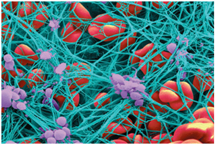
Figure 1 Shows agglomeration of platelets (purple) which convert fibrinogen into a network of fibrin fibers (blue) that stops the flow of blood.41
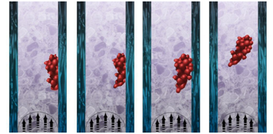
Figure 3
Analysis of the results supports the intuitive reasoning that as thrombus height increases, the shear stress that bloods exerts on the thrombus also increases as shown in Figure 4 through Figure 6. Here, higher pressure at the upstream side of the thrombus is observed at 0.5 H/D ratio when compared to H/D of 0.25 or 0.125. This happens due to the fact that blood velocity is higher as it approaches the center of the flow. This is caused by the reduction in the cross sectional area of the vessel due to the existence of the thrombus. Consequently, the interface between the thrombus and the vessel wall must undergo significant torque effects. Furthermore, the continuous pulsatile stresses applied at the surface of the thrombus will deteriorate it’s the mechanical properties at t >> 0.42 Likewise, locality of the thrombus along the vessel wall plays a key role in the triggering of the peel off mechanism and subsequent thrombus to embolus transition. Figure 7 through Figure 8 show shear stress profiles in which parameters for all three models have been kept constant, with the exception of thrombus location along the vein wall. Further analysis reveals a decrease in the shear stress by as much as 14% and 35% in the upper and central thrombus, respectively, when compared to the thrombus located at the bottom of the vein. In the same manner, clots that have formed with unsymmetrical shapes experience higher stresses than symmetrical thrombus as shown in Figures 10 & 11. Here it is shown that shear stress is as much as 25 % higher in the asymmetrical than in the symmetrical thrombus. Equally important, profiles for pre-hypertensive and hypertensive conditions support the congenital belief that shear stress increases at higher pressures as seen in Figures 12-14. This may not be the case in hypertensive patients suffering from SCD for the reason that their velocity profiles above normal would only reach normal physiological values due to the fact that their blood viscosity is higher.23 Consequently, thrombus shear stress profiles in the presence of SCD decreased substantially under normal, pre-hypertensive and hypertensive conditions as shown in Figures 18-20.
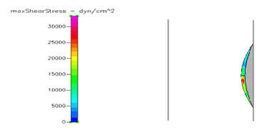
Figure 6 Shows the shear stress profile at 0.125 H/D ratio of a semispherical thrombus at the center of the vessel.
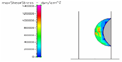
Figure 8 Shows the shear stress profile at 0.5 H/D ratio of a semispherical thrombus at the vessel lower end.
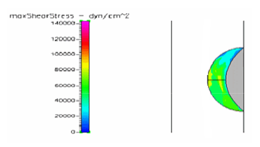
Figure 9 Shows the shear stress profile at 0.5 H/D ratio of a semispherical thrombus at the center of the vessel.
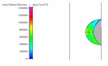
Figure 12 Shows the shear stress profile at 0.5 H/D ratio of semispherical thrombus at the center of the vessel with normal pressure.
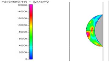
Figure 13 Shows the shear stress profile at 0.5 H/D ratio of semispherical thrombus at the center of the vessel with hypertensive pressure.
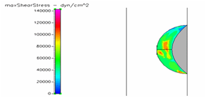
Figure 14 Shows the shear stress profile at 0.5 H/D ratio of semispherical thrombus at the center of the vessel with pre-hypertensive pressure.
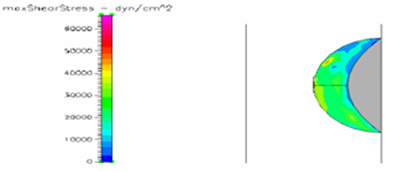
Figure 15 Shows the shear stress profile of semispherical thrombus at the center of the vessel with SCD blood viscosity.
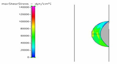
Figure 16 Shows the shear stress profile of semispherical thrombus at the center of the vessel with normal blood viscosity.
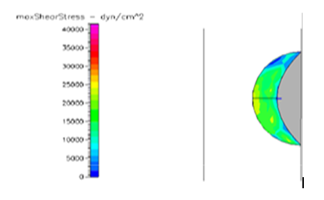
Figure 17 Shows the shear stress profile of semispherical thrombus at the center of the vessel with leukemic blood viscosity.
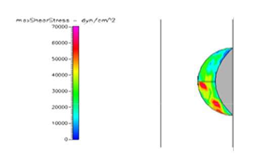
Figure 18 Shows the shear stress profile of semispherical thrombus at the center of the vessel with normal pressure and diabetic blood viscosity.
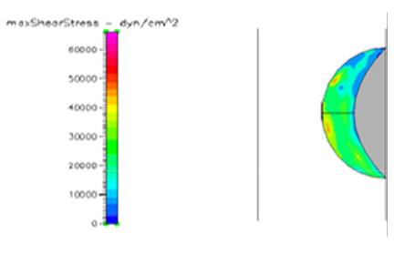
Figure 19 Shows the shear stress profile of semispherical thrombus at the center of the vessel with normal pressure and SCD blood viscosity.
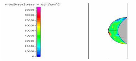
Figure 20 Shows the shear stress profile of semispherical thrombus at the center of the vessel with pre-hypertensive pressure and SCD blood viscosity.
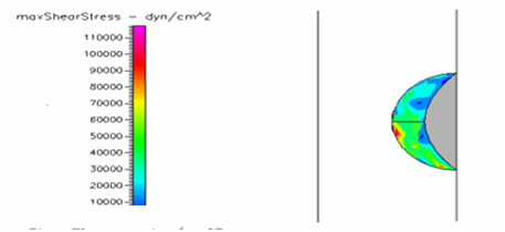
Figure 21 Shows the shear stress profile of semispherical thrombus at the center of the vessel with hypertensive pressure and SCD blood viscosity.
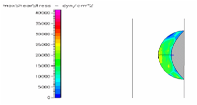
Figure 22 Shows the shear stress profile of semispherical thrombus at the center of the vessel with normal pressure and leukemic blood viscosity.
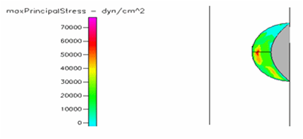
Figure 23 Shows the shear stress profile of semispherical thrombus at the center of the vessel with pre-hypertensive pressure and leukemic blood viscosity.
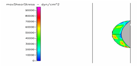
Figure 24 Shows the shear stress profile of semispherical thrombus at the center of the vessel with hypertensive pressure.
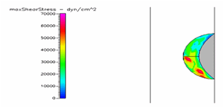
Figure 25 Shows the shear stress profile at 0.5 H/D ratio of semispherical thrombus at the center of the vessel with normal pressure and diabetic blood viscosity.
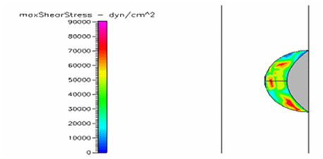
Figure 26 Shows the shear stress profile of semispherical thrombus at the center of the vessel with pre-hypertensive pressure and diabetic blood viscosity.
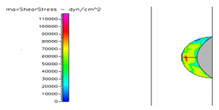
Figure 27 Shows the shear stress of semispherical thrombus at the center of the vessel with hypertensive pressure and diabetic blood viscosity.
Thrombus shear stress profiles for leukemic and diabetic viscosity have also been performed under normal, pre-hypertensive and hypertensive pressures. Leukemic viscosity has been reported to have reached values of about 6.2 cPoise or even higher.18,21 This is 70% more viscosity that normal blood. Figure 21 shows shear stress almost three times lower in leukemia than in normal blood. Furthermore, Figure 23 shows how leukemia, in combination with hypertension, only reaches maximum shear stresses of about 80000dynes/cm2 equivalent to normal physiological conditions. Although not as viscous as SCD and leukemic blood, diabetes mellitus also increases blood viscosity and it does cause less shear stress on a thrombus as shown in Figure 21 through Figure 23. However, there have been cases or extremely high viscosity in patients suffering from this disease.27,28 These findings point to the suggestion that thrombus would weaken slower, delaying the activation of the peel off mechanism, should it develop in conjunction with SCD, leukemia or diabetes. Further thought allows foretelling that thrombus to embolus transition in a leukemic patient would delay the most out of the mentioned complications. This may be of some value, although the effects of such conditions are not flattering at all towards the cardiovascular system having in mind that hypercoagulability conditions allows for higher blood viscosity which is chief among the causes of thrombus formation in the first place. A longitudinal study of these diseases about blood viscosity and thrombus fatigue may grant evidence for or against this hypothesis.
One of the principal achievements of this paper is the development a model that simulates blood flow through a vein afflicted with thrombosis by using CFD-GEOM and CDF-ACE+. It accounts for hemodynamic forces acting on the thrombus surface and vessel wall. It models the shear stress profiles acting on the thrombus and it allows varying its height, location along the vessel length, shape, blood pressure and blood viscosity. Results obtained from our simulations give a clear data of the risk of thrombus to embolus transition. A second important achievement of this study is the description of the peel off mechanism explained in detail in Figure 2. Here we proposed that activation of such mechanism occurs at t>>0. However, we have also determined that it could occur faster or it could be delayed as discussed in our results section. Our final achievement is the modeling of thrombus shear stress profiles under sickle cell disease, leukemic and diabetic blood viscosities as well as the simulations with blood pressure changes for normal, pre-hypertensive and hypertensive conditions for each of these diseases where their figures and results can be found on section 4 of this study. As cardiovascular conditions such as pulmonary embolism, stroke and myocardial infarction increase in the United States Population, so does the necessity for better diagnostic procedures and treatments. We hope that cardiovascular researchers benefit from this study as there is a need for scientific papers pertaining to thrombus-embolus transition.
This work was financially supported by the Norman Weldon Research Internship from the Department of Biomedical Engineering at Florida International University.
The author declares no conflict of interest.

©2017 Christie, et al. This is an open access article distributed under the terms of the, which permits unrestricted use, distribution, and build upon your work non-commercially.