Journal of
eISSN: 2572-8466


Review Article Volume 5 Issue 4
Department of Electrical & Computer Engineering, Khalifa University of Science & Technology, Abu Dhabi, UAE
Correspondence: Ahmed A Al-Durra, Electrical & Computer Engineering Department, Khalifa University of Science & Technology, Abu Dhabi, UAE, Tel 971 2 607 5511, Fax 971 2 607 5195
Received: August 07, 2018 | Published: August 29, 2018
Citation: Al-Durra AA. Survey of the state of affairs in diesel engine control. J Appl Biotechnol Bioeng. 2018;5(4):279-285. DOI: 10.15406/jabb.2018.05.00149
During the past decade, Diesel engine technology has stepped into the spotlight due to the great improvements made in materials, injection equipment, and emission treatment.1 These improvements allowed to mitigate the disadvantages of the Diesel engine which can be summarized as: low power density, increased level of NOx and particulate matters (PM), noise and vibration harshness (NVH).1 On the other hand, Diesel engines have the best fuel economy compared to the spark-ignited (SI) combustion engines.2 Furthermore, Diesel engines allow high boost at all engine speeds and load conditions with high efficiency and transient performance. In order to achieve all of these advantages as well as alleviate the disadvantages, good control strategies must be implemented to control the main important paths: fuel path, air path, and EGR path.3 In this report, the turbocharged Diesel control problems will be explored with some possible suggestions and ideas for more improvements.
Keywords: NOx, spark-ignited, diesel engine, recirculated, EGR
During the 1980s and early 90s, people used to look at Diesel engines as dirty and poor response engines with huge smoke and particulate emissions. Personally, I used to think of Diesel as the fuel for heavy load engines where we need high performance. The current generation of Diesel engines can achieve high performance in fuel economy as well as very low CO2 and smoke levels.4 In fact, Diesel engines have lower feed-gas emissions of the regulated exhaust gases; however, the high level of NOx makes the after-treatment devices for Diesel engines much less effective compared to the three-way catalysts in spark ignition engines (SI).5 Another important drawback in a typical Diesel engine is the low power density which is a result of the lean mixture that allows less fuel to be induced in the cylinder.3
The NOx emissions are a consequence of the high temperature in the Diesel cylinder (because of high pressure). To overcome this problem, part of the exhaust gas is recirculated through the exhaust gas recirculation valve (EGR) to the intake manifold. The recirculated exhaust gas decreases the combustion temperature resulting in less NOx emissions.6 The second problem (low power density) can be resolved using turbochargers which force more air into the cylinder; therefore, more fuel is burnt.3 Finally, we are left with the problem of noise and vibration harshness (NVH) which can be mitigated using the modern injection equipment such as the Diesel common-rail systems which use injection pressure of more than 108Pa.1,3,7
Control objectives
The main objective of the electronic Diesel controls is to satisfy a diverse set of confliction constraints imposed by: providing the required engine torque (steady state and transient) with minimal fuel consumption while meeting the exhaust emission laws.8 This will necessitate an optimal coordination of the EGR, turbocharger, and injection systems. Adding to that the complexity of the modern engine Diesel that includes, besides the reciprocating part, many other modules as shown in Figure 1.
There are three major actuating systems: the common-rail injection, EGR, and the VGT turbocharger. Obviously, the presence of three actuators in the engine plant (which is complicated by itself) introduces complex interactions between the subsystems. Therefore, it is essential to utilize a control strategy that must achieve the main objective with ‘high’ robustness; meanwhile, it shouldn’t use up much resources of the electronic control unit (ECU) and hopefully is simple to implement and calibrate.5 To show how hard it is to achieve all these objectives, the tendency of several input output relations are summarized in Table 1 where BSFC is the Break Specific Fuel Consumption. It is clear from the table that almost every input has a good and a bad effect on one of our objectives.
Control Input |
Consequances |
Early start injection |
Good BSFC |
Low PM |
|
High NOx |
|
High rail pressure |
Increased NOx |
Low PM |
|
little improved BSFC |
|
Smaller VNT area |
improved BSFC |
Low PM |
|
High NOx |
|
Increased EGR |
Danger of PM |
Lower NOx |
|
Improved noise |
|
Pilot injection |
Low noise |
Table 1 Tendency of Control inputs on BSFC, NOx, PM, and noise.3
The overall control problem
Figure 2 show a basic structure of a Diesel engine controller showing only the main inputs and outputs. We can divide the control problem into two stages: First, calibrating the reference input maps for the control loops to optimize the stationary performance of the engine. Examples of the reference inputs can be: start of injection, injection duration, common rail pressure, and EGR rate. A way to calibrate these inputs is described in,3 where the engine map is divided into different operating points each with a specific weight. Then, the objective function J is minimized with respect to all reference points where J is defined as follows:
(1)
The minimization is performed with the following emission constraints:
(2)
Another way to derive the reference inputs is do a minimization of the objective function similar to (1) but with respect to the control variables as shown in equation (3). Then, the control variables are related to measurable outputs via fitting functions. Therefore, by getting the desired value for the measurable outputs we get the control variables that will minimize the objective function. More details on this method are in.1
(3)
After getting the reference inputs for the control loops, the second stage of the control problem begins, which is the design feedback (and possibly Feedforward) controllers for the subsystems to achieve the desired dynamic response. Looking at the overall structure in Figure 2, we notice that there are mainly three paths: the fuel path, the air path, and the EGR path. However, the second two paths are much more interconnected compared to their relationship to the first path. The fuel path is ‘almost’ uncoupled with the others except for the air mass feed which puts a limit to the amount of fuel that can be injected to prevent smoke. Therefore, it is common to deal with the last two paths separately from the first path. This means that we can build two ‘almost’ independent control strategies: one for the fuel path, and another for the last two paths assuming that we receive the ‘optimal’ fuel injection mi and air-to-fuel ratio which can be considered as disturbances as we will see when presenting the proposed controllers for the EGR and the VGT turbocharged next section.
The variable geometry turbocharger (VGT) and the exhaust gas recirculation valve are controlled to regulate the set points of the air-fuel ratio and the amount of recirculated exhaust gas which depend on engine operating conditions. Many topologies have been proposed to solve this problem. Some of them treated the control of the VGT and EGR separately like in.9‒11 However, due to the interactions between the two actuators, most of the work done considers controlling both actuators in one control strategy, such as in.1,5,6,12 Furthermore, Many control strategies have been examined, such as sliding mode control in,9 nonlinear internal model control in,11 flatness based control in,13 nonlinear model predictive control in,6 constructive Lyapunov function control in.1,5,12 However, for all those control techniques, having a precise model is a key issue in fulfilling optimal control.
Model of turbocharged diesel engine
Almost all the proposed controllers are based on very similar third-order control-based models. Figure 3 is a simplified version of Figure 1 and it focuses on the VGT-EGR problem. At the bottom of the figure, we can see the turbocharger which consists of a variable geometry turbine connected through a shaft to the compressor. By adjusting the angle of the guide vanes of the turbine, we can change the flow rates and efficiency. This feature allows us to overcome the old problem of turbine overspeeding at high engine speed. The energy of the exhaust gas coming from the cylinders rotates the turbine (on the way out of the engine) and therefore the compressor rotates boosting the intake manifold pressure with fresh air. On the other hand, the other portion of the exhaust gas comes through the EGR valve and gets mixed with the boosted air in the intake manifold; then the mixture is pumped into the cylinder. The EGR cooler reduces the temperature of the exhaust gas which will help to reduce the combustion temperature, thus producing less NOx. The intercooler following the compressor helps to condense the air resulting in more power density as well as reducing the intake manifold temperature. The fuel is injected into the cylinder and burned, producing the torque on the crank shaft.

Figure 1 General Structure for a typical Diesel Engine.3
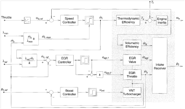
Figure 2 Basic Structure of a Diesel Engine Controller.3
In,5 an eighth-order nonlinear mean-value model was derived. This model is usually used as a benchmark for comparisons with the simplified control-based model. The simplified third-order nonlinear model in (4) was proposed in.12 It is derived using the conservation of mass and energy and the ideal gas law to model the pressure dynamics of the intake and exhaust manifolds as well as a first-order model with a constant delay to model the power transfer dynamics of the VGT with the isothermal assumption for the intake and exhaust manifolds.
(4)
Notation:
pi, px intake and exhaust manifold pressures
Pc,Pt compressor and turbine powers
Vi,Vx volume of the intake and exhaust manifolds
Ti,Tx intake and exhaust manifold temperatures
W1,2 mass flow rate from 1 to 2 as in Figure 3
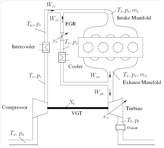
Figure 3 Turbocharged Diesel Engine.6
Vi,Vx volume of the intake and exhaust manifolds
Wf fuel mass flow rate
R specific gas constant
t time constant
The reader is referred to12 for the equations used to calculate the constants and variables in (4). Some estimation issues for these variables are discussed in.1 At this point, it should be mentioned that every proposed controller has more or less modifications to this model. There are some other control-oriented models such as the linear parameter-varying model proposed by,14 the model proposed by,8 which focuses on the effects of the scavenging efficiency which is neglected in many models, or the NARMAX model in,15 which is embedded to describe the relationship between the VGT command and the intake manifold pressure (gray-box modeling). However, the model in (4) is the most common model used for control.
Some proposed controlling techniques
In this section, several published control techniques for the VGT-EGR problem are briefly presented. For more details, the reader is referred to the original papers which will be mentioned accordingly.
Sliding mode control: Through the past two decades, sliding mode control has shown a great performance in nonlinear-systems control since it has excellent robustness properties. However, the main issue is that some systems cannot handle the switching effect. In9 a sliding mode controller is utilized to solve the VGT-EGR problem with a similar model as the one described in section 2.1. The VGT vanes and EGR valve are used to regulate the air-to-fuel ratio and EGR fraction to the set points optimized at each engine speed and fueling rates as in (1) which gives:
(5)
To facilitate the sliding mode design, an error system model is derived around the desired equilibriums as in (6).
(6)
This model is transformed into a regular form by splitting the space into two parts based on the direct effect of the input. A nonlinear coordinate transformation is performed rendering the system in regular form as shown in (7).
(7)
Wegr is controlled by a separate controller and treated as an external input (either open-loop or separate feedback). Therefore, is a function of the VGT vanes only. The sliding mode surface s is chosen to speed up the dynamics of the state as:
(8)
The results shown in the paper are very promising. However, the controller is not using the advantage of controlling both VGT and EGR in one controller. A question may arise here: will we have any chattering problems?
Feedback linearization based control: The feedback linearization control method was applied in.13 In the proposed control, the flatness property was introduced and utilized to solve trajectory planning. Basically, flatness property provides the system with a fictitious flat output, which can be used to explicitly express all states and inputs in terms of the flat output and a finite number of its derivatives.11 The controller set up is shown in Figure 4.
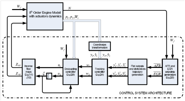
Figure 4 Feedback Linearization with Flatness Property.13
As in the sliding mode technique, the optimal set points of the AFR and EGR ratio are identified from experimental data and tabulated in look-up tables as in equation (5). The desired flat output and its derivatives are then compared to the actual ones and the difference enters the feedback linearization process. The resulting control inputs (Wegr and Wt) are passed through inverse flow maps to get the VGT vane command (θvgt) and EGR valve command (θegt).
The results of this technique do not look as good as the sliding mode. Furthermore, the controller assumes that all states are available for feedback which is not reasonable. Also, it is not clear how we get the flat output and how we know that the model (system) is flat.
Internal model control: The main idea of Internal Model Control (IMC) is to include the model of the plant in the feedback controller. If we have a ‘perfect’ model with no disturbance, this is nothing more than inverting the system in the feedforward control. In,11 the internal model control was used with the flatness property to control the VGT. The model used is different since it does not consider the EGR path and the main goal of the controller is to regulate the boost pressure only. The overall structure of the IMC with flatness is shown in Figure 5. where ω is the desired boost pressure and z is the (fictitious) flat output. The derivation of the controller is extensively explained in.11

Figure 5 General IMC structure with Flatness.11
The big advantage in this method is that it allows us to explicitly consider input constrains by mapping the constrains to the flat output. Furthermore, the paper claims that the method guarantees offset-free tracking. On the other hand, there are many assumptions that may not hold and make this method applicable only in theory. The biggest assumption is that the model does not have a time delay which is most likely violated in the Diesel engine with VGT.16
Nonlineal model predictive control: Model predictive control (MPC) is a common technique in the process industries such as chemical plants and oil refineries. Basically, it uses the models and current plant variables to predict future moves based on a set of feasible inputs. Based on a specific objective function (J), MPC chooses the policy that will result in minimizing (or maximizing) J without violating the constraints on the state variables as equation (9).
(9)
The work done in6 uses this technique to regulate the AFR and the EGR flow to desire set points similar to the previous methods. The method was implemented in simulation and compared to linear and nonlinear state feedback controllers. The predictive controller (Dynamic Programming) could achieve good transient performance while satisfying the input and states constraints. Nevertheless, it is not possible to implement MPC in real-time, since it requires a huge computational power on board of the vehicle which is not suitable. Furthermore, it needs a very good model to predict closely the future variables. Therefore, we can use the predictive control only as a benchmark for other feasible strategies.
Constructive lyapunov control design: In5,12 a control Lyapunov function (CLF) based nonlinear control design method is employed to regulate the air-to- fuel ratio and the EGR flow to a similar model as in the previous methods. The CLF is constructed using input-output linearization. Instability of the zero dynamics was an obstacle since the Diesel model is of non-minimum phase; however, redefining the outputs allow us to overcome this problem. Then, applying feedback transformation renders the system in the form (10).
(10)
The Lyapunov function in (11) has for specific choice of c1, c2, and c3. To get asymptotic stability we need which is achieved by a certain choice of and .
(11)
The authors claim, that the stability and robustness are guaranteed by applying a domination redesign control law which is explained in.5 Basically, the domination redesign is achieved by an appropriate choice of the positive scalar function when designing the controller of the form (12).
(12)
Two-stage tubocharger
In the proposed controllers in section (2.2), the limitations of the turbocharger were not considered except in the flatness control and the predictive control which are ‘almost’ not feasible. In fact, the turbocharged engine suffers from problems like turbo lag and boost threshold, which directed the researchers toward using various combinations of turbochargers (series, parallel, or both). In the study done in,10 an internal model control (IMC) approach is used to control a two-stage (series) turbocharged Diesel engine depicted in Figure 6. The turbocharger closer to the engine is called the higher pressure stage (HP) since it operates at higher pressure compared to the low pressure stage (LP) which is closer to the ambient. The low pressure compressor (LPC) is larger and optimized for high mass flows. There are three bypasses with variable cross-sections which gives more choices to optimize the air path. For illustration, the HPC operates at its optimum during low engine speeds, while it is bypassed at high engine speeds and the LPC delivers the necessary boost pressure.
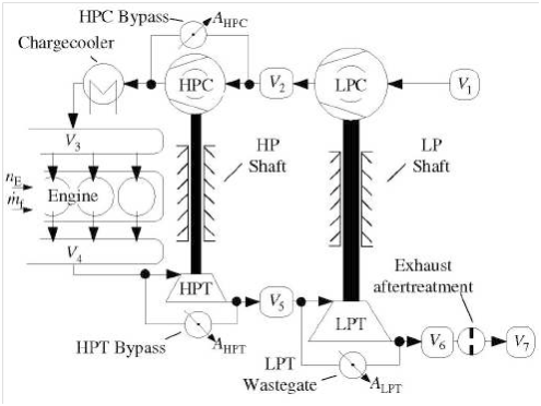
Figure 6 Two Stage Turbocharged Diesel engine.10
The control problem is defined differently compared to those in section (2.2). The variables to be regulated are the boost pressure p3, the exhaust manifold pressure p4, and the pressure of the chamber between the two turbines p5, while the inputs are the cross-sections of the bypasses.
13)
The engine speed Ne and the fuel mass flow are considered as known plant disturbances d. The control problem is to find the control input u, such that the measured control variable y follows the reference signal w. The overall structure of the IMC is shown in Figure 7. An affine model of 6-order is described in.10 The process to construct the controller is similar to the process carried out in section (2.2.3) (I/O transformation, then filtering the output to get its derivatives, etc).
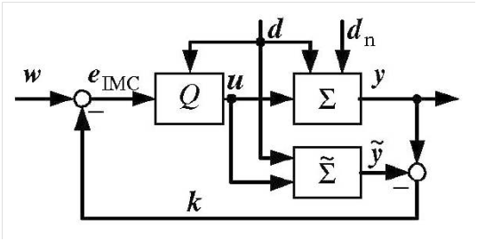
Figure 7 Overall Structure of IMC.10
The results of the simulation of this approach look outstanding. However, there are some concerns that are not clarified in.10 First, it is not clear where they got the reference signals (w). Are there no effects on NOx since we are not using EGR?
Other issues in air path controllers
In the previous section, several control strategies were applied to solve the air path control problem. Some were only theoretical and very difficult to implement. The major obstacles are the computational load and/or the availability of feasible sensors for certain variables. In this issue,1 has compared several controllers based on the complexity, measured variables, and computational load.
In section (1.2), we will touch this problem very briefly. In fact, the problem of speed control has been beaten to death during the end of the 1980s and early 90s. Many controllers have been proposed on the issue of fuel control, such as the H-infinity design in17 to control the Diesel fuel injection system, gain-scheduled controller in18 to regulate engine speed based on a set of linearized models obtained at different speeds and load conditions, or more recently the work done in19 to compare between the minimum variance regulator and the pole placement self-tuning regulator, both of which are applied to Diesel engine idle speed regulation. However, the paper in20 proposes a very interesting theoretical control strategy for a Diesel engine, where the method used is similar to the concept of sliding mode.
The overall picture of a basic engine speed and fuel injection control is depicted in Figure 8. The main inputs to the controller are engine speed (we) and throttle position (driver pedal) where the output is the duration and starting time of the fuel injection. The desired fuel quantity passes through a limiter that is based on a smoke map and a torque map. The smoke map is the air-fuel ratio limiter which tries to prevent smoke especially during the transients, based on the measured boost pressure or the compressor air mass flow as seen in Figure 2. The torque limiter decides the maximum fuel based on the engine speed.
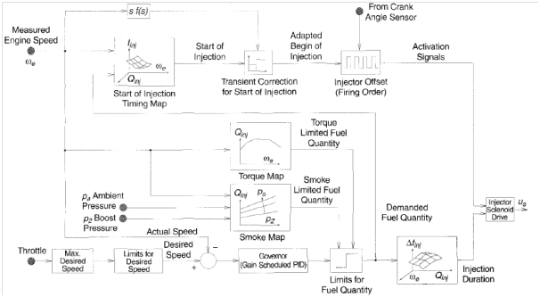
Figure 8 Basic structure for speed and injection controller.3
It should be mentioned that the calibrations for these maps required a significant effort in addition to the dynamic adaptation that is needed during the transient operations. An example of a map adaptation is the advance shifting of the injection during the transient, which will cause higher NOx for a small period of time but prevents smoke.3 To minimize the effort done in calibrations, several modeling techniques were proposed such as the one done in,21 which uses a linear grey-box approach to model the torque in response to fuel quantity-timing.
In this section, two different Diesel control problems are discussed briefly. The first problem is related to the control of the Homogeneous Charge Compression Ignition (HCCI) engine.22 The second problem is related to Hybrid Diesel engine control.
HCCI engines control
The Homogeneous Charge Compression Ignition (HCCI) is a form of internal combustion in which mixed fuel and air are compressed to the point of ignition. The HCCI has characteristics of both homogeneous charge spark ignition in a gasoline engine and the charge compression ignition in Diesel engines. The main advantage of the HCCI engine is its high fuel efficiency with low NOx due to the lower peak combustion temperature compared to the conventional Diesel engine.23
One of the most challenging issues in HCCI engine is the combustion phasing control. The HCCI engine doesn’t have a combustion initializer such as a spark plug (Otto engine) or fuel injector (Diesel engine). Instead, the combustion in the HCCI engine is achieve by regulating the temperature, pressure, and composition of the mixture.24 This complicates the control of this engine since it becomes very sensitive to any changes in the cylinder conditions. Furthermore, the properties of the mixture are awfully costly to be measured inside the cylinder which requires very precise estimator designs.24
Control of hybrid diesel engine
During the last 15-20 years, attention has been payed to hybrid electric vehicles (HEV) with the expectation that they represent a short- term improvement to fuel efficiency and reduction of emissions. Almost all of the applications of HEV can be utilized in both spark ignition and compression ignition engines. Some of the advantages are the following:
Furthermore, there are some new applications of HEV, such as the Start/Stop Control in which the electric motor/generator is used to help the engine during the starting or stoping phase. This improves the drivability of the vehicle and reduces the Noise Vibration Harshness (NVH).
The power split between the two power sources (engine and motor/generator) forms a big control challenge, which is called supervisory energy management control. Many techniques have been proposed to solve this problem.25 Guezennec & Yurkovich26 discussed several control strategies such as: Equivalent Consumption Minimization (ECMS), Adaptive Equivalent Consumption Minimization (A-ECMS), Control, and Dynamic Programming. However, it is difficult to guarantee the superiority of a method for all driving conditions except for dynamic programming, which is again not feasible in real-time.
In this section, I will present some ideas for some of the problems that we have discussed in this report, based on what I learned in my courses and some are just from my own thoughts:
VGT-EGR control
As we have seen, there are several techniques and topologies to solve this problem. Sliding mode control showed a good performance; however, it would be better if we could couple the VGT and EGR in one sliding mode controller. Also, I am curious whether we should consider any chattering issues from the switching effect. On the other hand, the Constructive Lyapunov Function control seems to be a good control, but I will need to learn more about the domination redesign control, which5 claims that it can guarantee robustness. On the other hand, the two-stage turbocharger looks like a neat problem; however, we would still need to incorporate the effect of the EGR.
Besides what is proposed in the literature, I am thinking of feasibleness of applying Model Reference Adaptive Control (MRAC). The problem is that the Diesel model is non-minimum phase which means that we cannot apply dynamic inversion. The way to go around this problem would be to define different outputs that will render the system minimum phase, since the zeros are a property of the outputs.
HCCI control
The most difficulty that HCCI engine control encounters is how to expand the region of operation over a wide range of speeds and loads.24 Gain-scheduled control or fuzzy control may suit well in this scenario; however, it is difficult to prove robustness with these controllers. Therefore, I am thinking whether we could apply hybrid engines here. We can control the HCCI engine to operate at specific points (speed and torque) based on the state of charge (SOC) of the battery. Then, the electric motor supplies the small deviation from the desired torque. Furthermore, we can use the Electrically Variable Transmissions (Planetary Differential Gearing) to control the speed.
Hybrid diesel engine
Section (3) indicates that during the transient, the injection is advance shifted to prevent smoke, but causes higher NOx. One suggestion would be to use the electric motor during the transient to alleviate this effect. Another suggestion would be to use the electric generator/motor to get a constant engine speed. Figure 9 shows a 4-cylinder engine speed with respect to the crank angle. It is clear that speed fluctuates within a range, and the mean value is what appears in the RPM gauge. The question is, can we use the generator/motor to absorb and produce torque and have a constant engine speed? If that is possible, then we can reduce the Noise Vibration Harshness (NVH), which will give us more freedom in designing the profile of the injection (pilot, main, secondary) to get less NOx and smoke.
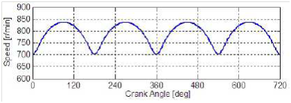
Figure 9Engine Speed vs Crank Angle.27
In this report, a summary of the state of affairs in Diesel engine control was presented. Three major control-related problems were discussed. Namely, i) VGT-EGR control, ii) engine speed control, and iii) HCCI engine control. We have seen that each one of these problems is very complicated and requires sufficient knowledge on the Diesel system as well as on control theory. Furthermore, potential control-related problems with the use of Diesel engines in HEV applications were briefly discussed. Then several brainstorming ideas related to these problems, some of which I learned in my classes, were discussed.
None.
Author declares that there is no conflict of interest.

©2018 Al-Durra. This is an open access article distributed under the terms of the, which permits unrestricted use, distribution, and build upon your work non-commercially.